So onto the meat and potatoes as we would say. It's a cold day up here and the shop is not that inviting when it's this cold. So we turned on the heater to get it at least up to a comfortable temperature.
Last time I talked about requiring measurements for mounting the Overhead drive assembly I picked up. Well I recieved measurements from two people that matched up within thous. So first thing I did this morning was measure out approximately where these holes would be in relation to the existing holes. The picture below shows the back of the lathe with the existing holes as well as 4 black circles where the new holes would need to be in order to mount the overhead drive. At this time I have a slight concern as to location of holes in proximity to the other holes as well as the total number of holes that would be in the back of the lathe when done. So I'm going to consult with the other lathe owners to see what the opinions would be on how to get around this problem. I'll brief you on the solution at a later date.

Previously I had started cleaning up the clutch mechanism from this overhead drive. When I took it apart and cleaned up the parts I found there was a company name stamped into the unit with a patent date. Here are a couple of pictures showing this data

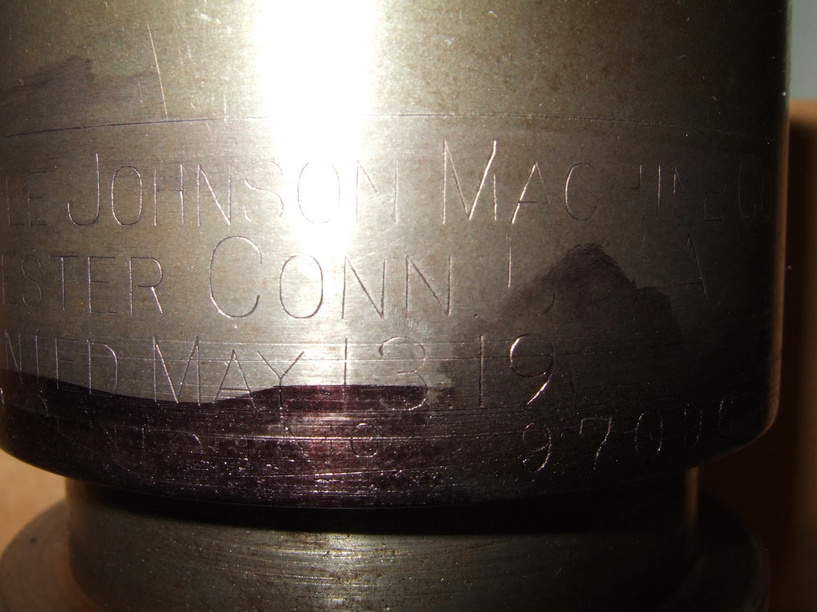

For clarity this is what it says " The Carlyle Johnson Machine Co. Manchester Conn USA Patented May 13 1902 Size 0 C***** No 97096" Unfortunately what is written in front of what I expect is a serial number is illegible. I spent some time on the web and eventually managed to find and print out the patent for this date for the company for this "friction clutch". I even found out the company is still in the business of manufacturing clutches and brakes.
I now took the cleaned parts and started putting them back together. Here are two pictures showing this.


In the first picture you can see the driveshaft with the selector mechanism that slides left or right depending on the speed required. In the foreground from right to left is the solid bearing, the outer clutch portion and the inner clutch portion with the spreading fingers. When these fingers are spread apart it grabs the inner wall of the second item and transfers the drive power to the drive wheel which is mounted on the right hand side of this item. You can see the complete assembly in picture two showing both the large and small sprocket for the two different speeds. Before setting this all aside I spent some time adjusting the fingers to I hope the right settings for the clutch to work. On the finger is a small screw that adjusts the cam blocks which provide the pressure to force the clutch apart. You can use these small screws to adjust the fingers as the clutch wears with use over time. I believe I have them set okay based on hand moving the outer sleeve mechanism back and forth however the final test will be when it is all connected up. The good thing is that these small screws are accessible once the entire mechanism is put back together.
Well that's all for this week. I hope over the next week to make a decision on how to mount the overhead drive as well I hope to purchase the steel required to make the "shake adjusting nut" I talked about a couple of weeks ago. Although I will be working over the holidays a fair amount will be on BB standby at home so I should have some time to work in the Shop over the holidays.
Well, have an enjoyable week and be careful on the roads, winter is here and the ice comes along with it.
That's all for now see you next week
Harold
No comments:
Post a Comment