


The first picture shows the lathe in the chuck after it was cut to diameter, length and had the head rounded over in shape of a rivet. Final operation operation was to drill a hole in the other end and to do this I needed to make a small sleeve that would go over the rivet body and then secure it in the chuck. The second picture shows this small collet. The slot was cut of course to allow the collet to squeeze the rivet and securely hold it while drilling the hole. The third picture shows the two pieces of the rivet. The smaller piece is a few thous bigger than the hole in the longer body and hopefully with some locktite and the interference fit will be a secure fastening for the hinge. The last photo just shows the long pin in the hinge for trial fitment.
Once this was done we could move on to drilling the two hole for the locking pins. First we set the base unit on the lathe and then carefully scribed a line vertically up the middle of the gap in the lathe bed onto the base of the mill. I then calculated where on this line I wanted to drill the hole. After a slight mis-start on the first base we drilled both of the horizontal holes. I then set the fixture up to drill the vertical hole which would intersect the horizontal hole. I lucked out in both cases and got both holes to intersect with most likely no more than 10 thous error. The Horizontal hole is .470" dia and the vertical hole is .750" dia. The vertical hole goes approx .650" deeper than the horizontal hole to allow room for the pin and a piece of spring. Here are a few photos showing the process.


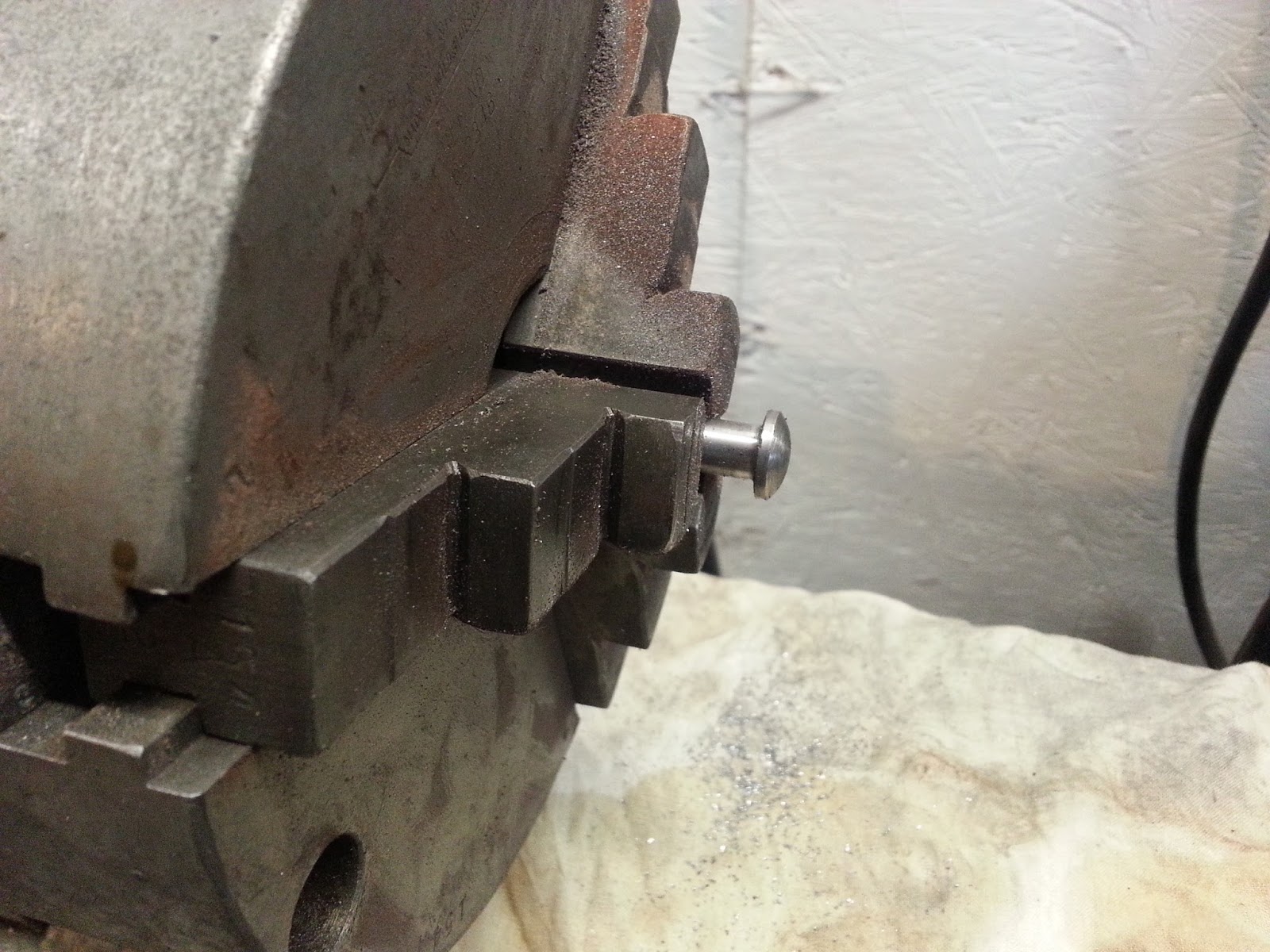
With the holes drilled out it was time to start working on the pins. Unfortunately I forgot to take pictures of the process so I only have pictures of the final product. We started by using a piece of 5/8" hex bar to make the horizontal pin. I initially machined done the surface of the pin area and once complete cut the whole length off. I inserted the pin side in the chuck and gave a slight rounding over to the head of the bolt. I made two of these and here is a picture of the results.

Next we turned to the Vertical pin. This was made from 3/4" round stock so required very little machining on the section that went inside the base. However the bottom end was turned down to .500" to accommodate the tread that would be cut later on. This smaller dia piece was then tapered up to the .750" size and then cut off so that we would have approx 5/16" left on the shaft after the cross hole was drilled for the horizontal shaft. I then placed the pin in the base and through the horizontal shaft marked where the through hole needed to be. Then prayed to the metal gods and drilled out the cross hole. Miracle of miracles after a little bit of filing it fit like a glove. Once this was done I decided to thread the shaft using the BSC thread dies I had and threaded a 1/2" by 26tpi thread. Once this was down we carefully filled down one side of the horizontal shaft where the vertical shaft crossed it. This would allow the vertical shaft to lower by the amount of material moved on the horizontal shaft due to the pressure of the spring above it. Then when the horizontal shaft is turned 180 degrees it raises the vertical shaft and thereby locks the base to the lathe bed with the assistance of a nut that still needs to be made. Here are some pictures showing the two shafts and how the interact with each other.


Unfortunately when I went out to purchase a piece of steel to make the nut plate I bought the wrong bar stock and will need to pick up another piece on Tuesday. However I did make a temporary nut to try it out. It worked however I am a little concerned that the thread might be to fine a thread for the usage. Once I make a proper nut I will assess the working of the assembly. My worse case will be to make two new vertical shafts and thread a coarser thread on it, most likely 1/2-13tpi. However we'll see how it goes later this week. Even with this minor issue I was quite happy with all the work done. I'm just glad that it worked as expected. Like Hannibal Smith said " I love it when a plan comes together"
Well that's all for now and we'll see you either end of March or earlier If I get the two units finished sooner.
Harold
