Saturday 23 November 2013

Well we have success. After a week of spraying Liquid Wrench over it every day the "shake adjusting nut" finally came off. However it did not go without a fight. I had to force it every step of the way until the last few threads. I think that when they made this the tolerances were so tight that just a little bit of junk was enough to bind it up. There was no obvious rusted areas however there was one line in the nut which was as a result of galling. I'll include a few pictures here of what I mean.


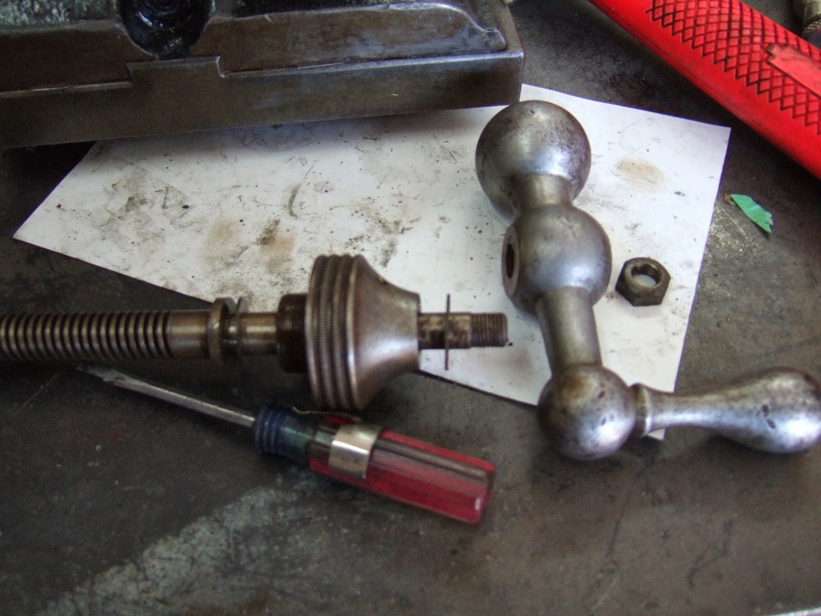
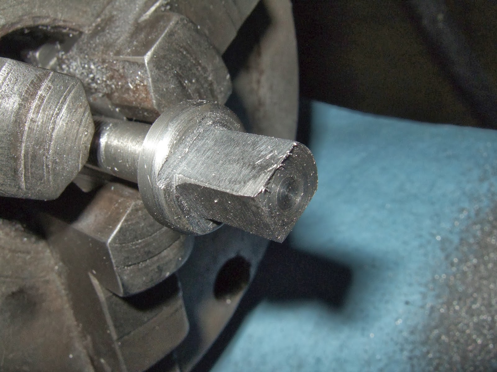
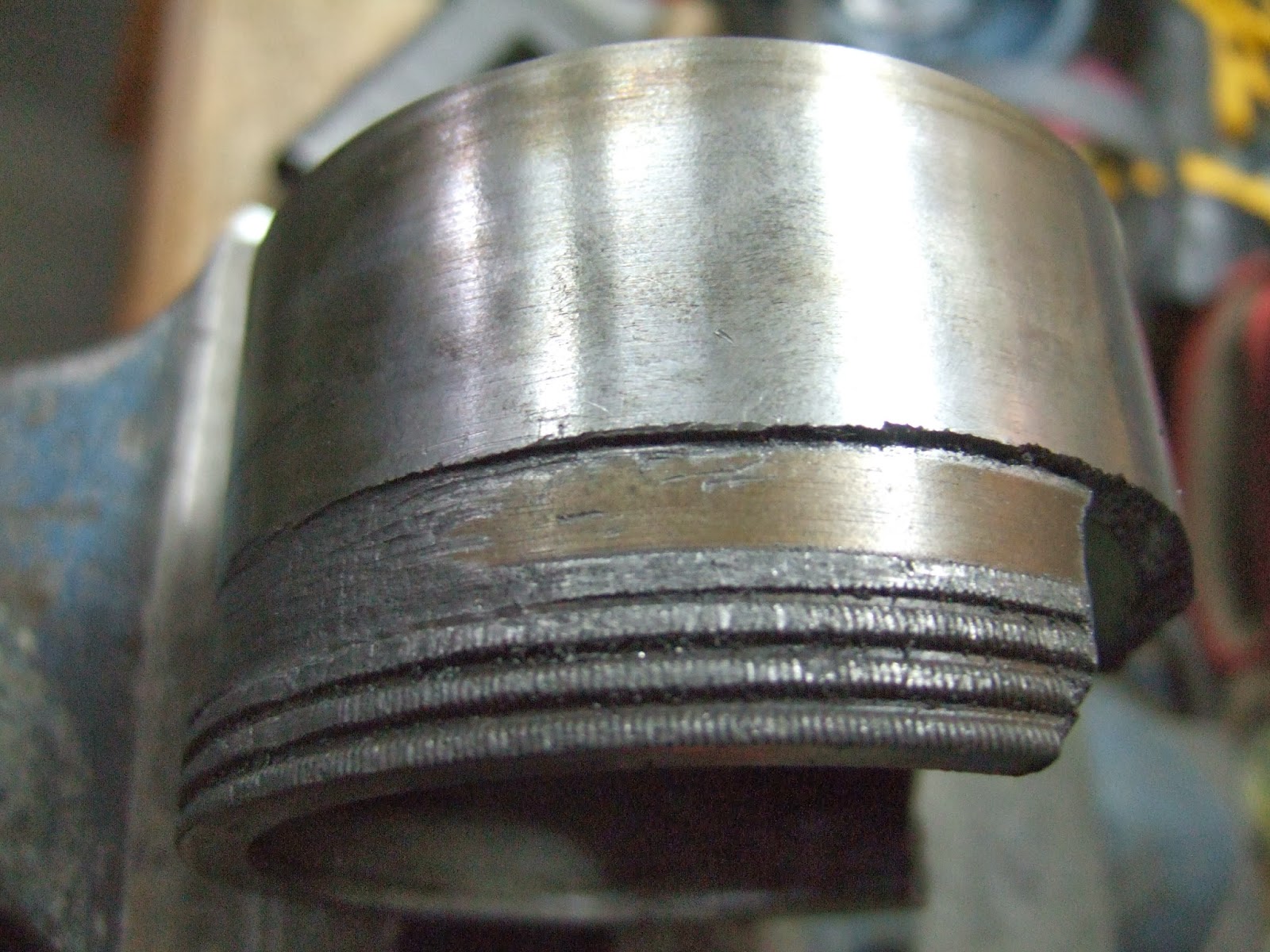
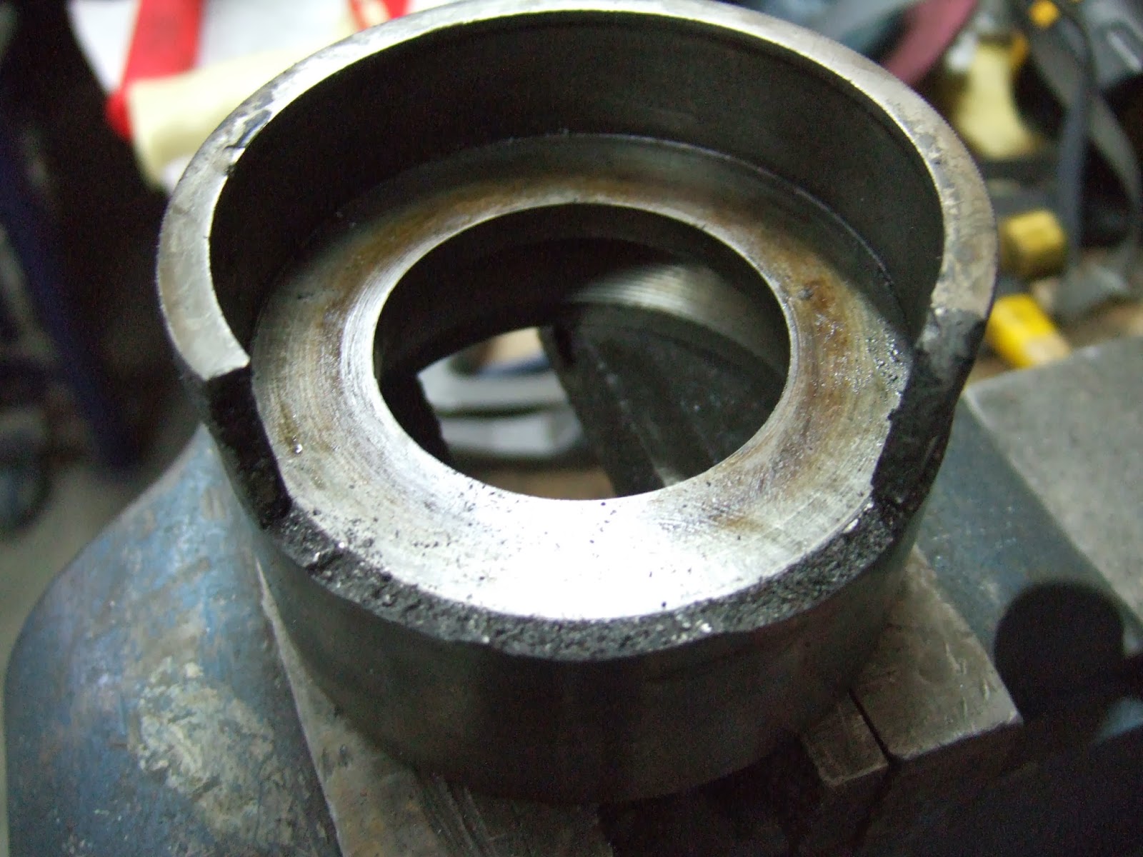
In the first picture you can see the galling line halfway up the side of the nut. The nut is threaded on the inner portion. You can also see the damage I created with a special wrench to try and remove the nut. I bought a very large Channel lock plier used on 3-4"Pvc pipe. It has three gripping areas. In the second picture you can see the fracture line where more of the nut flange is waiting to break off. In the third picture you see the pocket where the thrust washer sits. You can also see some of the threading if you look through the shaft hole to the back of the nut. I have decided that I will buy some new material and make a new "shake adjusting nut" If this works well, I will also make a new one eventually for the #39 lathe as that one is damaged as well. All I need to do is decide what material to make if from. The original was Cast Iron however I'll probably use some 12L14 steel instead to make the new nut. Now that it is all apart I can look at putting this all back together. However this will have to wait until I make the new nut and get back from some vacation.

Since all I did with the headstock was spend a few seconds a day rotating it and spraying it with Liquid Wrench I decided to do some more work on the overhead drive. It took a little tinkering but I managed to get the transmission assembly out of the casting. This was facilitated by removing the end caps and then carefully removing the plain bearings from each end. The shaft was then loose enough to slide side to side to allow the removal of two brackets which were used to hold the three step pulley in the proper location. Here is a picture of the assembly.

You can see the two brackets one is still on the left side and the other is laying on the bench by the larger drive sprocket. You can also just see the flat bearings on the shaft at either end. The assembly between the two sprockets is the actual transmission area. A "u" shaft rides loosely in the groove in the centre and moves the larger tube either left or right for low or high speed. I'll attach a few pictures and then talk about the parts that are in this assembly.


The first picture shows the sliding mechanism. in the second picture is a inner piece that is secured to the shaft by a set screw. In the second picture you can see a small screw and plate that was removed to allow the tube to slide off. When this is secured on the inner piece with the tube in place the tube can only move left or right a fixed amount, about 1 inch. On either end of this assembly is another assembly that slides on, this is in picture three above. The item in picture 4 is the inner part of this assembly. When the tube in picture 2 slides left of right there is a small stub piece of metal inside the tube that slides the 2 arms from picture 4 apart. Because of the cam effect of the two small blocks at the bottom of the arms it spreads the collar apart and locks it inside the outer assembly you see in picture three. This would then drive that sprocket. When the tube moves the other direction these two arms would come back together releasing its collar and the two arms in the same assembly on the other side of the shaft would seperate to do the same work and therefor grip its assembly and drive the gear on that side of the assembly. Because of the two different sized sprockets we have two different speeds. Hopefully when I get it all back together it works as advertised. My only concern is if the small collars that spread out get too worn then they will not lock with the outer assembly. If this happens then the drive assembly will not work as advertised. I will not know this until we are all done rebuilding the overhead drive assembly, so wish me luck with this.  Just to give you a sense of all the parts in this entire assembly here is a picture of all the individual parts of this transmission shaft assembly.

Once this was all taken apart I made up a quick little tool to help in removing the threaded spacers that were located in the bottom end of the casting where it bolts onto the lathe body. These spacers can be threaded in and out to compensate for the roughness of the lathe body casting as well as to properly locate the overhead drive right above the headstock. Here is a picture of the spacers before removal.

Once these were removed I put the dust mask and my face shield on and took two days to clean all the old paint off the casting. Once it was all cleaned and wire brushed to remove any surface rust we gave it a spray with a rust inhibiting primer. Here you can see a picture of the casting covered in primer.

There are three people that own these lathes that also have the same overhead drive assembly. I've asked them to send me pictures of how it is mounted as well as measurements for where the holes are in the lathe body. I need these as my lathe never had this overhead drive  mounted and there were no factory holes for this assembly. My hope is that these people send me measurements that match each other so that I can use those same measurements to install mine. If not then I will wait until the headstock is mounted and carefully calculate where it needs to be mounted to ensure its smooth operation.

I will be taking a break from the project as I will be heading home to visit Mom for the next two weekends. So the next time that I'll write in the blog will be 15 December.

For all you Americans out there have a happy Thanksgiving and a safe shopping day on Black Friday.

All the best
Harold

Sunday 17 November 2013

Well hello again from my workshop. Did not manage to do much during the week other than try and disassemble the "shake adjusting nut" from part of the headstock. This is the name that the Hardinge brothers gave this piece and it was supposedly patented, however I have not found that particular patent yet. Twice I went out in the shop and heated the part with a propane torch and attempted to loosen the nut. When nothing happened I just heated it up again and then stuck it back in the varsol to soak some more. For those who don't quite know what I am talking about here is a picture of the item. The nut is the inner piece which has a part broken off similiar to my other lathe. Inside the broken ring is where the thrust washer would sit and then when the nut is threaded out it would put pressure on the washer against the headstock casting thereby securing the headstock properly. The back piece that this nut threads into is a casting with one side of the gearing that engages the back gear, as well as being able to secure the headstock for machining work in 60 different positions. There are 60 indexing holes drill around the edge.

On Saturday it was such a nice day here that I cut the grass one last time before the snow flies and then I had to spend an hour or so with a person who came and bought my Bowflex Ultimate 2 home gym. I wasn't using it anymore and since I plan to move next spring I am slowly trying to get rid of items I no longer use thereby reducing the amount of stuff I need to move. What little time I did spend in the garage was to start work on tearing apart the overhead drive assembly that I bought from a fellow down in California. Here are two pictures showing the whole assembly from the side and then looking at the gearing and step pulley assembly.

First thing I did was remove the door covering the drive assembly and the small adjusting lever you can see in the first picture. I then removed the two chains. I noticed that the previous owner had just secured one of the chains with wire as the outer plate was no longer there and on the other chain there was safety wire as well however at least this plate was still there. Once this was done I removed the two bolts that held the three step pulley on its adjustable bracket and then removed that assembly. You can see the empty cavity where it resided and then you can also see the assembly in the next two photos.

This was as far as I got on the drive on Saturday. Today I decided to once more try taking that stubborn nut apart. Still no luck. This time I have it sitting on the bench and I am spraying and soaking penetrant fluid on it wherever I can get it to see if that helps. If this does not work I will then have to think about drilling some holes that I can place pins in and see if we can't lever the part out that way. However first we'll continue to soak it with penetrating oil for the next week. With this out of the way I decided I might as well strip clean and paint the headstock casting. Nothing difficult about this just time consuming using commercial stripper and then cleaning it in Varsol. Once that was done used the wire wheel to strip the remaining paint and rust of the casting. Then taped it up and gave it a coat of primer. Here are some pictures showing these steps.


I almost forgot that there was a small pin on the headstock casting that would be the stop for the lever that controlled the back gear assembly. This pin was broken off flush with the casting. Carefully punched and then drilled it out. Here is a picture prior to drilling. This was a fairly simple procedure as well. Later on we'll make up a new 5/32" pin and locktite it in the hole.


Well that's all for now see you next week Sunday. Hopefully I'll have some good news on that stuck nut. 

Harold

Saturday 9 November 2013

Not exactly the busiest week in the shop. Managed to get a few things done however.I also am going to need to redo one of the items I worked on. It's the old proverbial two steps forward one step back. Oh well I have the time and it will give me better experience working on this lathe.
I decided that now that the tailstock was done I would finish the split nut that goes under the gearing section on the end of the leadscrew. Previously I had made the circular part and threaded it for use. However I could not bore the countersink and drill the holes for the nuts on the Van Norman mill you'll remember because I did not have a vise. I also could not cut the nut in half without this same vise. Well when I came home last week I stopped at KBC and bought a vise. A little sidebar here. I only wanted a 4" jaw vise which weighs in around 50lbs. I did not want the 6" because the physical vise is to large and it weighs 100lbs. They had two vises in the catalogue at reasonable prices. One was KBC branded the other was no name. Of course the no name was 100$ cheaper. The write up however was identical. So I asked the salesman what the difference was. He said the KBC was made in Taiwan the other in China. Well since I'm not in the business of making money I decided to go with the no name one. Big mistake. It will work, but I already see shortfalls with it and I've only used it 1 hour.
So with vise installed I mounted the split nut so that I could bore out the countersink and drill the holes for tapping the bottom half of the nut once separated. Once both sides were bored and drilled I began to setup for cutting the nut in half. I quickly realized that I could not use the vise and therefore fixtured it to the bed of the VN#10. With the head in horizontal mode and a thin cutting blade installed it was short work to slice the nut in half. Here are some pictures showing these steps as well as the finished product.

 Now to install the nut. First problem noticed the bolt heads were to high and hit the gearcase casting. So over to the drill press to bore the counter holes a little deeper. Still didn't work. One of the other reasons it did not work was when I took a close look at the original bolt they drilled the hole so that it was on the thread side of centre and mine ended up being on the away side of centre. So either make a new one or think outside the box. I decided to shorten the heads of the bolts so that they would clear. This is not the ideal solution so somewhere down the road I'll pick up some more 2" stock and make a new split nut and be a little more careful with the measurements. However for now it is bolted on and spins with no interference.

Once this was done spent a little time around the shop cleaning up and then decided to take the Headstock apart. Before I took it all apart I took two pictures for the before shots. Here they are. One thing to take away is that on the left of the second picture you can see a hole just to the right of the casting bracket and the left of the gear. This will be talked about later.

Next we removed the back gears. This was not to problematic and they came out fine after a little head scratching to remember which way the internal shaft came out. Once that was done next step was to remove the gear on the left side of the headstock which drives the "transmission gears" and then to remove the brass bearing covers. These brass covers were on tight. I had to go out and buy another tool to take them off. Once they were off, and one took a little more oomph than I wanted to use. I've decided that I will most likely have to make two new ones. One especially is damaged badly from previous owners and then me trying to remove it. Here's a picture of the damage.

 Once that was done I removed the four screws that hold the three step pulley to the headstock shaft. I don't have a picture of this but on the largest dia flat pulley section there is a cap screw you remove and then through the resultant hole you can access four screws. These have tapered ends that lock the three step pulley to the headstock. Once the four screws were removed I decided to remove the pin that locks or unlocks the pulleys when using the back gears. This pin can engage in two different spots on the three step pulley and has a small screw retaining it in place and a spring and ball bearing underneath the pin shaft that locks it either open or closed by detents. Unfortunately I forgot how tense that spring was and when the pin was pulled our she flew. Luckily I found the spring within a few minutes. The ball bearing is somewhere in the garage and I'm not crawling around to find it. We'll just find another ball bearing some where. I then tried to release the nut that holds the thrust ball bearings in place. In second picture of the headstock I talked about a hole. This hole is in a part that threads out or in from the three step pulley. This covers a three piece ball bearing system, two races and a ball bearing cage. By turning on this cover you either place more pressure on the bearings or by loosening you relax the pressure on the ball bearings. This is done to allow the headstock to rotate between the two main bearing housings without being to sloppy. Unfortunately I cannot at this stage unscrew this item. So at the moment it is sitting in varsol and hopefully later this week I'll be able to take it apart. At the opposite end is a fibre washer or at least that's what I assumed since that was the setup on my other lathe the #39. On this lathe the washer at the opposite end was metal. Here's a picture of this washer. There are marking on it but no real galling or grooving so it seems to have worked.

I then removed the two cast iron bearings from each end of the headstock and then gently tapped out the headstock shaft. Once it was all out a careful inspection shows very little damage to the headstock shaft and slight scoring to the cast iron bearings. But on the whole they are in good shape. I should be able to just hone out the cast iron bearing and possibly just clean up the shaft. Here are some pictures showing the upper and lower shaft and the cast iron bearings.


 Once we had the shaft out all the rest of the parts from the headstock came out relatively easily. This headstock is in very good shape, everything is very snug, not like my #39 which needed a lot of work to make the headstock usable again. This one should need just a thorough cleaning and then oiling up the parts before reassembly. One thing that I found interesting was that whatever oil that was used previously was quite thick and smelly. I would have assumed they would have used spindle oil on the entire headstock however most of the parts were covered with a relatively thick oil. Another interesting discovery was that under the second step pulley is a cavity that according to the blueprint should hold felt to keep oil in there. On this lathe the cavity was empty so no felt to absorb and hold the oil. Here is a picture of this as well as the blueprint picture for those who would like to see a drawing of the headstock.

Once everything had been taken apart some went in the varsol bath some went on the table awaiting the varsol bath. I'll leave you with a few shots of all the pieces spread out.


Well over the next week I hope to get a chance to slowly work on cleaning the bits and pieces as well as painting those parts that need it. 

Well for those of you from the Commonwealth that take time to reflect on November 11th I hope you have good weather on Monday. May your thoughts go out to those that gave up their lives so that we can live in relative freedom. 

Harold


Saturday 2 November 2013

Well after spending some time with Mom helping clean up Dad's estate I'm back home for the time being.
Spent some time in the shop working on refurbishing the tailstock for the #86 lathe.
I'll start by showing you some pictures of the tailstock before it was taken apart.

The tailstock was in pretty good shape at least looking from the outside. However once we started taking it apart some small issues came up. First thing I'll say is that this tailstock was assembly #78 which by my thinking means it came from lathe #78 however that may not be the case either since some other assemblies don't seem to match up with the lathe serial numbers. However here are two pictures showing the tailstock serial number

Now when we started to take the tailstock apart the first issue was noticed. The tapered spreader bar which you see above with the serial # stamped in it was cracked by one of the clamping holes. Thankfully this looks worse than it actually is. The bar still can be secured in place and the two pieces will actually stay locked together due to the type of break it is. Here is a picture of what I mean.

You can also start to see the effects of the second problem. The second issue was the beginning of rust wherever there was metal to metal contact. The picture above shows the rust under where the spreader bar would be and the picture below also shows the rust that was found when I split the tailstock in two pieces. This picture also shows where there were 4 pieces of shim stock used to raise the tailstock to bring it into alignment with the headstock. 

Thankfully all this could be cleaned up with a razor blade and some fine sandpaper. Once everything was stripped down to their component parts we could start cleaning them as well as painting any parts that needed it. Once that was done we could start putting it back together. Here you can see a picture of most of the parts waiting to be reassembled.

Part of cleaning and prepping the parts also entailed polishing any bare metal that would remain exposed and would not get a continuous coating of oil. I was quite happy that when we put it all back together the tailstock ram has negligible slop for a tool this old. Just for ref here is a picture of the parts of the ram mechanism.

Another thing I learned while working on the lathe was that the clamping nuts which are just square blocks with a threaded hole in the centre had a small hole with a screw and brass plug that would lock the block on the threaded bolt and prevent it from turning if you removed the tailstock from the lathe. On the #39 lathe these holes are in the blocks but there were no screws and plugs so I guess will have to make some up some day. These locks sure help in keeping the clamping setup secure at all times. Here is a picture of the block and the small screw and plug.

The last thing I'll talk about is what I call the cross slide bolt. This bolt moves the top of the tailstock in or out to line it up with the headstock. On the # 39 lathe there were two screws one in front and one in back that you threaded either in or out to move the tailstock in or out for lineup. On this lathe there was a long bolt with a allen nut threaded in the end. I knew that this could not be original so contacted another Lathe owner to see what he had. He advised me that his bolt was longer than mine and had a nut on the end where I had the allen nut. Here is couple pictures of this bolt.


The first picture is the original bolt, the allen nut was threaded in the left end. There should have been another 3/8" of shaft and it should have been threaded to accept a nut. Now by turning the bolt and either loosening or tightening the nut you move the top part of the tailstock in or out. Tightening and loosening the bolt and nut have to be done together to get the operation to work. The second picture shows the beginning of the new bolt and the original one above it for reference. You can see the new bolt is longer and has 5/16" threading on it to accept the nut. The third picture shows the bolt in a sacrificial nut that I made to be able to hold the bolt while turning the other end. The fourth picture show the results of filing down three sides to make a square bolt head, still need to file the fourth side. The fifth picture shows the completed bolt with the new nut lying above it and the original bolt lying below the new bolt. Once installed it all worked like it should. Once everything was together I placed it on the lathe and here are some pictures showing it mounted on the lathe.

There are only two things left to do. One make a brass dauber that fits in the hole on the back of tailstock and two once the headstock is installed find out the height difference between the head and tailstock and reinsert shims to bring the tailstock into alignment with the headstock vertically. Of course we'll also have to loosen up the cross slide bolt and adjust the tailstock in the horizontal plane as well.

Well until next week have a great time

Harold