I started by placing the bottom piece of the steady rest on the milling machine and machined the base of the steady rest. This required milling level the two "feet" bottoms and then milling the inner flat portion that lays on the top of the lathe ways. Once that was done I could machine the sides of the two legs to 60 degrees to match the side of the lathe ways. I used a shell mill for the flat portion and then a 60 degree horizontal milling wheel for the leg sides. Here are a few pictures showing the machining operation and then the final fitment on the lathe itself. It did require a little tweaking with a file to get the base to sit nice and firm on the lathe ways. First picture shows me getting the holder parallel to the cutting head. Second shows the two legs flattened and the centre flat machined as well. Third shows horizontal wheel to widen the flat and then the fourth picture shows the 60 degree cutter in action. Last pictures shows the bottom of the steady rest on the lathe after tweaking.


Once that was done I turned my attention to the top half of the steady rest. First I started work on milling the "inner tang" of the pivoting mechanism. I made this tang .375" thick and would then mill out the appropriate slot on the lower half. When I first made the patterns for casting the steady rest I built the patterns from a whole lot of pictures of an original steady rest and a few dimensions. When I started maching the top section I machined out the slot where one of the steady rest fingers would go. I initially thought the fingers were about 1" wide and possibly 1/2" thick. With this in mind I machined out the first slot. I have since learned the fingers are only about .8" wide and around 3/8" thick. This was brought home when I started to machine the finger slots on the base unit. Anyway I milled out the slot 1" wide and approx .375" deep. I also milled flat the closing tang. Here in the first picture you can see the 1" slot being milled out. For ref I was running at around 100rpm, feeding in by hand with a 50thou depth of cut. It actually worked really well. In the second and third picture you can see the tang being formed by milling off the two sides to get my .375" wide tang.

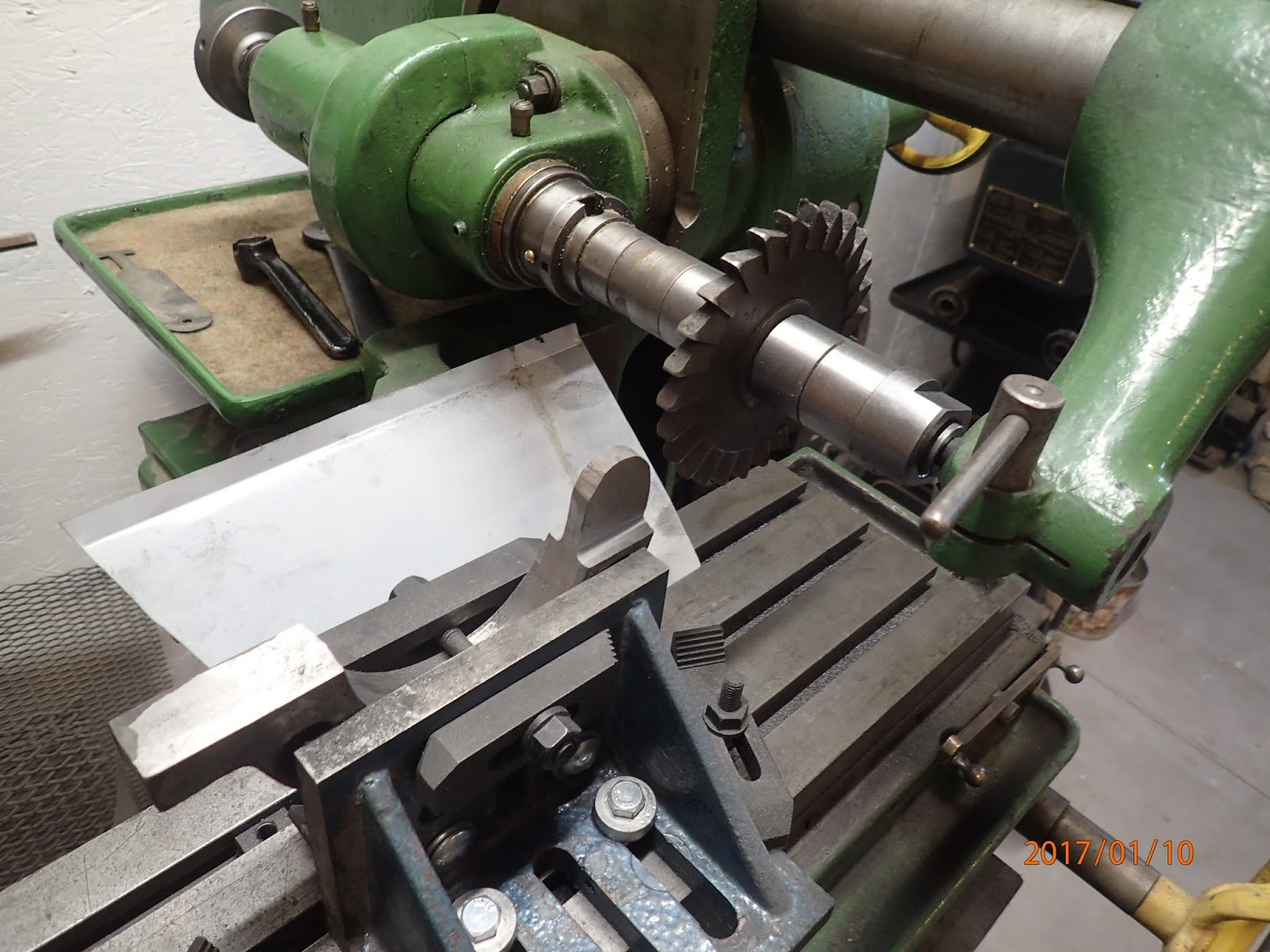
We now went back to work on the lower half. First we milled out the groove to accept the upper portions tang. I also milled flat the portion that would be part of the closing apparatus on the other side of the steady rest. With that done we started work on milling the grooves for the fingers. I first milled the groove on the latching side of the rest. Once I started work on this groove I realized that I had a width problem and would only be able to mill out a groove about .8" wide. Oh well not an issue, however when I got around to milling out the groove on the other side where the pivot mechanism was I realized that the groove could only be .75" wide and only .25" deep due to the slot I had cut out for the upper tang. After looking at it a bit I realize I can mitigate some of this on the next steady rest by one cutting all the fingers only .75" wide and going .300" deep by realigning how I cut the groove. I initially cut the groove horizontal however it I cut it on the same angle as the finger I have more meat left at the inner side. That was the problem with wider and deeper finger slots. I would intrude into the groove I cut for the pivoting mechanism. So here are some pictures showing the finger slots being milled out as well as showing how I supported it during these operations.


Once this was done it was time to thin down the locking support tangs. First I thinned down the upper halfs tang and then worked on thinning out the lower halfs tang. Once both were thinned down to the same with I place the entire unit back on the mill to be able to machine flat the upper portion of the tang on the upper half. Here are some pictures showing the entire process and the use of wood as a securing strap.


So in the mean time I've ordered some bearing bronze to make the fingers and all that's left to do would be to bore out the holes in the finger area for the locking nuts and the adjusting nuts. Lastly we would need to bore the holes and machine the lockdown mechanism that secures the unit to the lathe. Well that's where the title of todays blog comes into play. I went into the shop this afternoon and decided to bore out the longitudinal hole where the locking shaft would go into. I wasn't thinking to well and one I mad the hole to big and two some how I got it off centre such that the lower half is now a useless 8lbs of cast iron. Just for reference here's a picture showing the lower half sitting on the lathe. The hole you see needs to be centred on the gap in the lathe bed and it is not.

Well I think I'll drown my sorrows in a glass of scotch and then head off to bed. Work comes a littler earlier tomorrow morning. All the best and hopefully next time I write an update I'll have better news.
Harold