Saturday, 4 January 2014

Well welcome to the New Year. 2014 is now officially here and we are not enjoying the start of this New Year. Lousy weather all over the place. Bitterly cold weather here. Some people might say I have nothing to complain about considering their location and temperatures but -25deg C is really cold for our area. Now they're talking about another snowstorm tomorrow as well. Oh well at least I have a heater for the garage although I'm sure the hydro company loves it when I turn it on.
Anyway on to the continuing story. So I contacted my friend with the drill press however his chuck only goes to 1/2" as well. He suggested I could come buy and use the mill with collets as he has collets that will fit the 3/4" shank on the countersink. However by the time we had discussed this I had decided to buy a new chuck for my drill press that will accept 3/4" shanks. I should have this chuck by the middle of next week and then I will be able to drill the countersinks required in the mounting plate.
Now I know I said I didn't want to start on something fresh as I already have lots of parts laying around waiting to be reassembled. However I could not just sit around especially with all this free time around the holidays. So I decided it was time to take the section apart that held the 3 step pulley in the overhead drive assembly. This section takes the driving motion from the "transmission section" above and translates it down to the headstock by way of a 3 step pulley. The transmission has a high and low setting and using this with the 3 step pulley gives you 6 different speeds at the chuck face. Once  the entire lathe is assembled and the electric motor installed with appropriate pullies I will be able to chart the 6 speeds. Here is a picture of this section of the overhead drive. You can see the 3 step pulley as well as the two sprockets which accept the chain drive from the transmission shaft.


Just a little side trip here. The two sprockets above are for a "leaf chain" that comes from the transmission shaft above. These two chains each have a connecting link. However the one chain was missing the closing plate that completes the link. I cleaned up the link and found out the manufacturer was Whitney chain which was bought out by Renold in the mid 1940's. I emailed the company as well as a few other leaf chain manufacturing companies to see if I could obtain an appropriate connecting link plate. Below is the picture of the link I sent some companies as well as a picture of the leaf chain.


The picture of the link shows the details of the link with sizes. Although a .375" pitch chain is still made the pins on the links are now .140" in dia not the .100" dia pins that I had. So, so far nobody has been able to help me with finding a premade plate. So I decided to make one up myself. I took a piece of steel from a tie down strap that had broken and cut out enough to make the plate. First thing I did was carefully file it down to the thickness required. Then we carefully filed out the profile like the original link plate. Once we had something that was close I drilled out the two holes and made sure it fit on the connecting link as needed. Here are some pictures showing the different stages of work.


Once we proved it fit I heated the part up cherry red and quenched it in some water. Then we heated it again to a lower temperature and let it cool down naturally. It wasn't a precise heat treating job but based on what i've read and seen it should do the trick. The last picture above shows the two links, one with original plate attached and the other with the new made plate after heat treating lying beside it. So at least the chain will be secured properly. All that is left is to buy some really small cotter pins to pin the plate to the other half of the link.
I then went back to working on the previous piece. I disassembled the speed change lever and cleaned an painted this section as well as polished on part of the lever. Only thing left on the handle is to give the wooden end a few coats of Tung Oil. Here are some pictures of these pieces. Looks like the previous user of this drive painted this handle and another one read probably to make them a little easier to see.


Next was to take the parts that held the shaft with the 3 step pulley and the sprockets apart and clean all the pieces. Once they were all clean they were primed and painted. No real issues with any of this other than the mess when wire wheeling all the parts. There was a little paint left on the metal as well as a base coat of some material that basically came of as a black dust. Some form of metal filler is my guess. By the way the original paint looks like it was a "lime green" tint. Here are some pictures of the parts getting cleaned and painted.
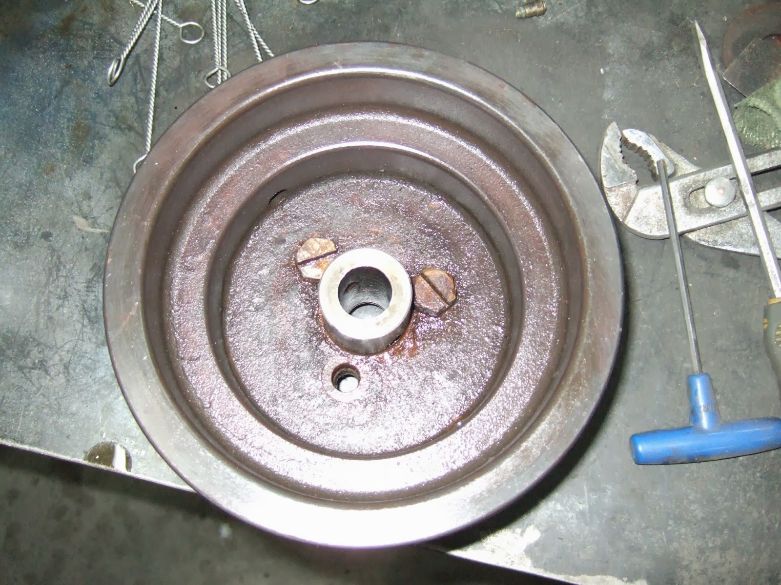


A couple things that came up. In the first picture above you see there is a bolt missing, not sure what happened there as I'm not even sure how they bolted them in. Could not use a socket or a wrench. Could use screwdriver since there is a slot in the head of the bolt however it does not look like it would turn around without hitting the centre shaft section. I did not try and unbolt them to prove this however it is the only way I see they could have done this. Along with this one of the two bolts installed had a lower profile head to allow an Allen set screw to be used. This set screw had to be inserted prior to the bolt being inserted. You can insert an Allen key to tighten and loosen however you cannot take out the set screw. Another interesting thing was there were Allen set/cap screws used to secure the pulley and the sprocket to the the shafting. At first I thought they must be an after market repair as I thought Allen screws were not around when these lathes were built. However after doing some research I found out that accepted knowledge says the first manufactured Allen screws occurred around 1910 although some patents go back into the 1860's.
I started to put this assembly back together today, Saturday, however I wanted to freshen up a couple of the Allen set/cap screws. Unfortunately the local hardware stores did not have my sizes in stock so will have to wait till Monday when the local Fastenal store is open and we can pick them up there. As well I can also order the small cotter pins I will need.

So that's where we sit at this time. Hopefully by next week the new drill chuck arrive and I will have bored out the countersinks. Then we can really work at putting this entire overhead assembly back together. On a little side note for those who might be interested. I was talking to an individual in Chicago who was interested in my Van Norman #10 Dividing head. According to this fellow he used to own one of these Cataracts and sold it to another person in the area. I have asked him if he remembered the Serial number but he did not. However he did say he still is in contact with the person who purchased the machine so hopefully over the next few weeks he has a chance to talk to this fellow and I hope he contacts me to see if his is a new serial number or one we already have on the charts.

Well until next week have a great time enjoying this cold and white weather.

Harold


Saturday, 28 December 2013

Well Christmas has come and gone, and as the retailers would say only 362 shopping days left till next Christmas. I hope you all had a great time with family and friends and I hope that the New Year celebrations will also be a time of great fun. Please remember don't drink and drive.
Well the weather improved since last weekend. We had a lousy weekend in regards to snow and ice. The Airfield here was even closed due to the ice accumulations for almost 3 days. This allowed me to go in and pickup the metal I had ordered previously as well as purchasing the 1.25" countersink I would need and the extra drill bits I would need. I didn't do much during the week due to celebrations, some work and clearing snow and ice away around the house.
What little I did during the week was again clean, prime and paint a few small pieces. This time it was the lever that moves the transmission shaft left or right for high and low as well as a lever that moves the second three step pulley up to tighten the belt. Here is a picture of these two parts.


Today I spent some time installing the two plates that would mount on the lathe and accept the studs that would hold up the overhead drive. First I cut the 1/2" by 4" plate to length, approx 11" for the top piece and 7" for the bottom piece. After rounding the corners and dressing them up a bit I placed it on the lathe to calculate where the first hole would go. Once held in place there was quite a bit of rocking around on the bottom plate so took out the large sanding wheel and carefully ground down a high spot on the lathe. Once this was done the plate laid up against the lathe body a lot better. After a little calculation based on the measurements received from two other lathe owners I drilled the first hole. The plan was to keep the piece on the drill press after drilling the hole so that I could drill the countersink at the same time without moving the piece. Unfortunately the countersink has a 5/8" dia shaft and my drill press only has a 1/2" dia capacity. Oh well I'll talk to a friend and see about going to his shop and drilling the countersinks out there.
Without the countersink I still went ahead and drilled out the remaining holes. First I spray painted the back of the plate so that I could scribe the holes from the back side. I then took a clothes hanger and cut it apart. I ground the one end down to a point and then placed a 4" 90deg bend in it. I then slide that down the inside of the lathe and carefully moved it around in the existing hole to scratch out where I would need to drill the hole on the plate. I then took the plate off and used a washer drilled out to 5/8", the size of the bolts, to assist in locating the centre of the hole, I then centre punched and drilled out the hole. I then mounted it back up and carefully filed out the hole such that I could insert the bolt. I did this three times for the upper bracket and once for the lower bracket. The upper bracket covered 6 holes that were in the lathe body however I've decided only to used the outer 4 holes to mount the plate. The lower bracket had only two holes but after looking at this I decided to drill one more hole and tap this to accept the 1/2" bolts that will mount the lower plate. Here is a picture showing the two plates installed. The upper bolt in the lower plate is the new one I drilled and tapped in the lathe cabinet.


You should be able to tell that they are not countersunk yet. Once I get them countersunk I will carefully scribe where the upper right mounting stud should be based on measurements and installed this stud. After that stud is installed I will support the overhead bracket and slide it onto the stud so that I can position it to be able to mark out where the other three studs need to go. This job will be for another week as I first want to countersink the plates.

Well until the next installment have an enjoyable week and Happy New Year to all.

Harold

Saturday, 21 December 2013

Well I'd hoped to be able to show you the steps I took to making a transition plate that would mount to the existing holes and then be setup so as the overhead drive would mount to this plate. After discussion with some of the other lathe owners the decision was made to buy some 1/2" steel plate and carefully drill out holes in the plates to match the holes in the lathe body. I would secure this plate to the lathe using countersunk bolts. I would then drill holes into the plate in the location where the mounting holes should be to hold the overhead drive. These holes would be slightly under 1/2" dia. I would then chamfer the back of the hole and place a chamfer on the stud that would go into this hole. I would then carefully press the stud in and weld this stud in place. With all 4 studs properly secured I would mount the two plates and then mount the overhead drive on the 4 studs. By doing it this way I do not drill any extra holes into the lathe and thereby do not compromise any more of it's integrity.
So that was the plan however mother nature got in the way. I had placed an order with the local metal supplier for some round stock for the "shake adjusting nut" as well as some flat stock for this transition plate. However on Friday when I was supposed to pick it up we ended up with the start of an Ice storm. So far we've had I believe the better part of 10-15mm of ice accumulate on roads, vehicles, trees etc. So I was unable to pick this metal up. This storm is expected to finally end late Sunday so looks like a fairly quiet weekend will be had. No reason to go driving so we'll stay nicely at home. Because of this I cannot do much this weekend. I hate taking too much stuff apart too far in advance so I'm not going to strip more pieces apart. About all we did this week was clean up a few parts from the drive. I've cleaned and painted the two bearing caps and I've cleaned and prepped two hangers for their primer and paint. Here are the pieces I am working on. The two bearing caps are on the left on the wood plate and the two hangers are on the right warming up before priming today.

Well I hope to be able to pick up the metal on Monday and then be able to work on this stuff over the next week. More news next week.
To each and everyone of you  Merry Christmas and a Happy New Year. May you all have a wonderful Christmas season.

Harold

Saturday, 14 December 2013

Well I'm back at home after spending some time with my Mom and the rest of the family. Since we are of Dutch descent we've always had a little celebration for St Nicholas Day, this year we had all the family together and celebrated this day instead of getting together on Christmas as I will be working then. So for all you Dutch people or of Dutch descent "Prettige Kerstdagen en een Gelukkig Nieuwjaar".

So onto the meat and potatoes as we would say. It's a cold day up here and the shop is not that inviting when it's this cold. So we turned on the heater to get it at least up to a comfortable temperature.
Last time I talked about requiring measurements for mounting the Overhead drive assembly I picked up. Well I recieved measurements from two people that matched up within thous. So first thing I did this morning was measure out approximately where these holes would be in relation to the existing holes. The picture below shows the back of the lathe with the existing holes as well as 4 black circles where the new holes would need to be in order to mount the overhead drive. At this time I have a slight concern as to location of holes in proximity to the other holes as well as the total number of holes that would be in the back of the lathe when done. So I'm going to consult with the other lathe owners to see what the opinions would be on how to get around this problem. I'll brief you on the solution at a later date.


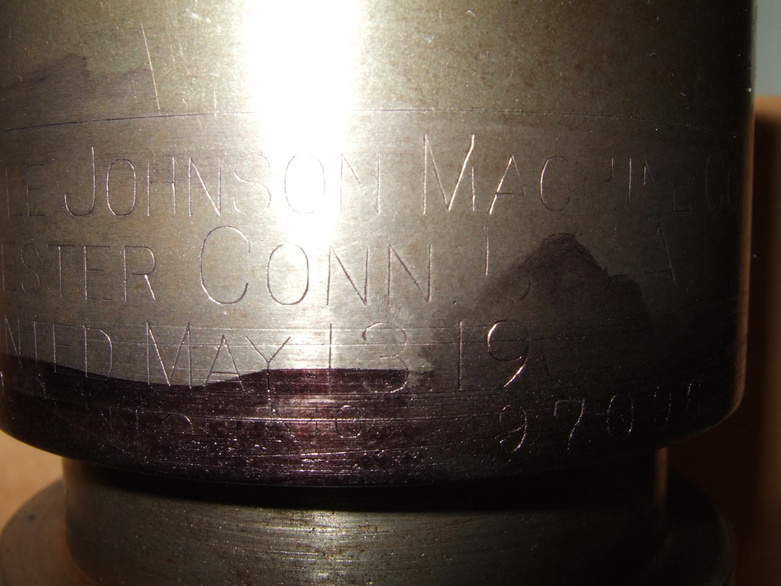
Previously I had started cleaning up the clutch mechanism from this overhead drive. When I took it apart and cleaned up the parts I found there was a company name stamped into the unit with a patent date. Here are a couple of pictures showing this data


For clarity this is what it says " The Carlyle Johnson Machine Co. Manchester Conn USA Patented May 13 1902 Size 0  C***** No 97096"  Unfortunately what is written in front of what I expect is a serial number is illegible. I spent some time on the web and eventually managed to find and print out the patent for this date for the company for this "friction clutch". I even found out the company is still in the business of manufacturing clutches and brakes.
I now took the cleaned parts and started putting them back together. Here are two pictures showing this. 


In the first picture you can see the driveshaft with the selector mechanism that slides left or right depending on the speed required. In the foreground from right to left is the solid bearing, the outer clutch portion and the inner clutch portion with the spreading fingers. When these fingers are spread apart it grabs the inner wall of the second item and transfers the drive power to the drive wheel which is mounted on the right hand side of this item. You can see the complete assembly in picture two showing both the large and small sprocket for the two different speeds. Before setting this all aside I spent some time adjusting the fingers to I hope the right settings for the clutch to work. On the finger is a small screw that adjusts the cam blocks which provide the pressure to force the clutch apart. You can use these small screws to adjust the fingers as the clutch wears with use over time. I believe I have them set okay based on hand moving the outer sleeve mechanism back and forth however the final test will be when it is all connected up. The good thing is that these small screws are accessible once the entire mechanism is put back together. 

Well that's all for this week. I hope over the next week to make a decision on how to mount the overhead drive as well I hope to purchase the steel required to make the "shake adjusting nut" I talked about a couple of weeks ago. Although I will be working over the holidays a fair amount will be on BB standby at home so I should have some time to work in the Shop over the holidays. 

Well, have an enjoyable week and be careful on the roads, winter is here and the ice comes along with it.
That's all for now see you next week

Harold