While I was home this week I managed to do a few small items. First the Taper attachment as mentioned is all cleaned up and ready to go. Here is a picture of it laying on the bench awaiting install.
Now lets get on to the new stuff we did this week. On top of the gear housing are three gears that translate the power from the headstock to the gearing section. The first gear sits on a shaft where it can move in and out 5/8" so that it can either engage the rest of the gears or not. The picture below shows this gear assembly.
Next I decided to start working on the locking collar that sits on the extension to the leadscrew under the gearing section. Here is that same collar on the #39 lathe that I will need to duplicate.
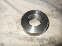
This collar is approx 2" in dia by approx .650" thick. I had no 2 inch stock in the garage so had to turn down a piece of three inch to the required diameter. Once that was done I drilled out as much as I could with drill bits on hand and then parted off the piece to the correct thickness. Once the part was removed I placed it back in the lathe and proceeded to bore out the hole until the appropriate size was acquired to allow me to thread it for the 1" by 26tpi thread that is on the shaft. I finished that all, and was going to go to the mill to start boring out the holes for the retaining screws when I realized I have not yet bought a vise for the Van Norman milling machine. I've been actively trolling Ebay and other sites hoping to get an actual Van Norman vise to go with the machine but so far no luck. I guess this weekend when I drive home will stop by KBC tools and pick one up. I leave you with two pictures of this part. One while still in the lathe and being turned down to correct diameter and the second when it was done and awaiting milling.
I also took the time to install the change gear bracket which we had cleaned up last week and started painting. Here is a picture of it back in place.
Last thing I did this week was machine a shoulder bolt and nuts for attaching the forward/reverse pivot arm to it's retaining bracket below the gear housing. This was a fairly routine piece as long as you measured twice to ensure you had the right length for the shoulders otherwise you might compress the bracket and prevent the lever from working smoothly. Here are two pictures one showing the bolt and nuts after machining, and to be reasonably authentic they are 5/16" by 26tpi which was common on this lathe. Second picture shows the bolt installed and working as it should.
Well tomorrow is Thanksgiving here in Canada and it's a holiday for us Canucks. My guess is that I will most likely spend a little bit of time in the shop working on the Tailstock for the remainder of the week. I hope those Canucks reading this enjoy your Thanksgiving Turkey and for all you Americans it's just around the corner for you. As for the rest of the world you can have turkey whenever you want. It's good all year round. All the best and enjoy the fall weather. It's been great up here so far.
Harold


Harold-
ReplyDeleteThis threaded collar that you made... I have been told that sometimes this collar will self-tighten, and bind up the shaft. If this happens, the 3-change lever can break it's casting. This happened to my lathe (presumably) and my 3-change lever had the 45deg ear broken off that mounts the idler gear. So take great care that the split on your collar is tightened tight, and the self-screwing action does not happen. I have seen other lathes like this with the same 3-change lever bracket damage. ---Doozer