Sunday, 28 April 2013

What a difference a week makes. Today we hit 22C finally the warm weather starts to arrive. This will be a good week to work on the lawn and work in the shop with the door open allowing the sunshine for come in.
Actually had a couple of good days working around the shop and the house. I believe I've reached the stage where the wood patterns for the shelf supports are as good as they need to be. All thats left is to put a few coats of shellac on the patterns. I'll attach a few pictures showing some of the work stages. First picture will show gluing the curved back onto one piece. Next picture will show gluing the two pieces together to form one half of the pattern. The third picture will show adding some stiffeners in and the last picture will show the filler used to fill in the corners and round out some areas for the taper required on the pattern. Next week I hope to have a few pictures of the completed pattern after the shellac has been applied.


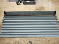
Over the last two days I started working on the rails that are required for the collet tray to ride on. I'm making two sets since Bruce in Toronto would like a set for his lathe as well. First thing I needed to do was pull off one sample from my #39 to use as a template for the parts. The rail is made of two pieces of angle iron one 3/4" by 3/4" and the the other 1" by 1". After cutting out the pieces to the appropriate length and bending tabs over on the 1 by 1's I had the pieces needed. Here's a couple of pictures showing the parts laid out and closeups of the riveting they did to mechanically fasten the two pieces together.


 Now I thought about just welding the parts together but to try and be as historically correct as possible I decided to rivet the pieces together just like the original. After spending some time on the Web trying to find places that sold rivets that would be usable and could be shipped easily I gave up and decided to make my own rivets. Went down to the local Canadian Tire store and picked up a length of 3/16" and 1/4" rod. After I got them home looked at the originals and decided that the 3/16" was the size required. Figured out I would need 1/4" of grip length and 1/4" of stickout to make the tail. So picked up a piece of Scrap cast iron I had in the garbage bin and drilled a countersunk hole to use to form the rivets. Drilled a small 3/32" hole in the bottom to be able to push out the rivet once formed. Cut 22 pieces of the 3/16" rod 11/16" long to make the rivets. Then using a cheap Mapp gas/Oxygen torch heated the rivet up to cherry red and then pounded the top down while in the hole in the cast iron to form the countersunk head of the rivet. Here is a picture of  one rivet and the rivet former and then all 22 rivets that were formed. This gave me two spares.
 Now they are not perfect as you can see but I'm sure they'll work for my project. Due to the nature of the cast Iron I needed to drill three holes to use as forms as the countersunk area was getting damaged after 5-8 rivets. While they were cooling down I drilled and countersunk the rails to match the original. Then got out the torch heated up the tails and one by one pounded them down to rivet the two pieces together. Once all 5 rivets were in stalled carefully used an angle grinder and a die grinder to grind the countersunk heads down so they were flush with the rail face. Here are a couple of pictures showing the completed riveting job on one piece and then a closeup of the countersunk side after a quick coat of primer and then one more showing the completed first piece. Now only three more to go. Will have that done tomorrow morning in about 1hour.
Even though I did not have all the correct tooling it was still nice to see that once down it looked very similar to the original piece.


Well that's all for this episode see you again in another week of so.

Harold

Sunday, 21 April 2013

What a miserable week we've had. Cold, damp and dreary. Needless to say was not the kind of weather that moves you to do anything but huddle up with a good book or a movie.

I still managed to get some work done on the pattern for the tray supports though. No pictures to show since the work was monotonous and there's really not many changes to show. It involved carefully filling in all the fillets and smoothing out the joints. This meant apply some filler, let it dry over night and then sand it down. Now repeat the process at least 4 times to build up some of the areas and then ensure you still have the slope required by the foundry to cast the metal. I hope to be finished this process tomorrow with the last of the sanding and smoothing. Once that's done I will install the locating pins to ensure the two halves align properly and then we'll start shellacing the pattern. I expect this to also take the better part of a week as I place one coat on per night. Then when dry 24hrs later, a light sanding before the next coat is applied.

My hope is to have all this done, such that I can bring it to the foundry by last week in May. This will match up with when I go to my parents before we all drive out to Kalamazoo MI to visit my Grandmother who this years turns 101years old. We'll visit about 5 days and then return. Once I come back I will bring back the overhead drive I bought from California and had shipped to my cousins in Kalamazoo. As to whether the foundry will be finished not sure. Last time they took three weeks from when the pattern was dropped of to when the parts were ready.

Well all the best with all of you and enjoy the week ahead.

Harold

Saturday, 6 April 2013

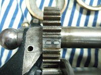
Well we're into April and the temps up here are finally going to start climbing. They say we should hit 15C by the middle of the week. This will definitely improve the working conditions in the workshop. Well I guess I should start by saying that the #39 Hardinge is back in action. I reassembled everything oiled it all up and ran it up. After 5mins no issues and the bearings were not getting to hot. So cross your fingers this will stay fixed for a long time. While I had it apart I decided to try and fix the broken gear tooth in the back gear assembly. One tooth had been broken off before I got this lathe and although the lathe worked I decided now would be the time to fix it. I used the method whereby you drill and tap a few holes to take a couple of small bolts. Loctite the bolt in the hole and then carefully grind and file it to the correct profile. Here are some photos showing the repair. First one shows the two holes drilled and tapped. Second picture shows the profile once filed from the side and the third picture shows the filed teeth from the top. Once I ran the lathe there was no noise from this repair and if anything there was less noise as it ran nice and smooth when the back gear was engaged. This also gave me practice for the work on the #86 lathe as it has a few broken teeth.

 I also decided to machine another bolt for the pulley to headstock fixturing setup. As you can see by the picture below one of my original bolts did not have the complete tip to engage the hole in the headstock. So picked up some drill rod, turned it down, and made a new bolt.  Here is the picture showing the 5 bolts including the bad one.
One other note, when I was running the lathe after repair the belt was quite a bit noisier than before. I previously had quite a bit of noise and managed to negate most of it by moving the upper pulley around. Unfortunately it cannot move any further and there was still noise. I remember somebody on one of the forums mentioning baby powder on these continuous rubber belts. Sprinkled a little baby powder on the belt and no more noise. So I guess the can of baby powder will stay close by in case the noise reappears. Once that was done I cleaned up the lathes covered them up and went back to working on the wooden pattern for the tray support bracket.

This pattern is definitely trickier than the last one I did however most likely still easier than the next one I need to do to make a pattern for the follower rest. So spent a few days fiddling with wood and glue to make up the bits and pieces and slowly start putting them together. I have most of the lower tray support done and it is mated with the part that has the holes that locate the mounting hardware. I am in the middle of gluing up the upper tray support which will then be mated with the lower support. When all is done there will be two halves of the pattern and the whole bracket will be split down the centre. When finished this will become clear. The first picture shows the upper shelf bracket clamped up while the glue dries, the original bracket is being used as weight. The lower bracket assembly is to the right in that picture and you can see the separation between the two halves. The second photo shows me holding the lower bracket assemblies roughly in the location where they will be so that you can see the pattern is slowly coming together. The third picture is just another view showing what the pattern will roughly look like once finished.


Well that's all for this week I hope you enjoy the coming week. There will most likely not be a weekly installment next week since I'll be visiting the parents however I hope to cross the border and head towards Rochester to look at another Hardinge QC headstock that we are aware of and that the owner wants to sell.

Harold