I decided that the first thing I would finish off was fixing my cross feed assembly on the #39 lathe. I finished cleaning up the cross feed assembly from the lathe that was parted out in California the #77 and reassembled it for installation in my #39. After installing it I noticed that there was no change the cross feed assembly was still very stiff to turn. I had originally thought that the repair work I had done was the cause of this stiffness. So since I was still using my original Bronze nut I decided to try the #77's bronze nut. Unfortunately that one would not fit my lathe, it was a little to high to fit in the slot on the carriage. Went back to my nut and with out locking it down ran the handle full out and in and it worked fine. Looked at the nut and realized that there were small grooves down each side on the top. Evidently over time the nut had some how been grooved and therefore when tightened was pulling the thread up and therefore uncentreing it. Placed a few shims on the top of the nut reinserted it and tightened it up and the cross feed assembly worked fine. Decided to reinstall my original assembly and with the shims on the nut this assembly worked as well. Maybe not as smooth as it should be but more than acceptable for me. So at least that was done.
Once this was all fixed used the lathe for the first time to thread by making the bolt that will hold the collet tray up to the spindle. Here are two pictures showing the threading process and the final product.
The treading system works very well just need to be carefully how you set it up being so close to the chuck. Unfortunately I did not measure very well and the bolt was 50thou undersize, so will need to make another one. That was the first 2 steps back but not a real issues since this was giving me good practice in threading on this lathe.
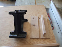
At this time I decided to fix the carriage rack since the original rack with my #39 was worn in the area when you are close to the chuck. This was one reason I bought the carriage rack from the #77. Well I learned a few things installing this carriage rack. Evidently not all Hardinge Cataract QC parts are interchangeable. First I did find out that the carriage rack can be turned end for end and used again. However mine had already be done and there were two wear spots in the same spot from both ends. Evidently sometime previously they had already flipped the carriage rack. This was also confirmed by the lack of pins between the screws that would hold the rack in place. When I went to put the rack from the #77 on it would not fit. The holes would not line up on my lathe body. On careful examination I saw that the new rack was .5" longer and about .125" higher than my original rack. Now the question then is was this an original Haridinge rack or was this a replacement made by some one else. On my rack the serial number was stamped on the new rack there was no serial number stamped. However this rack was installed on the lathe in California so we have a mystery. When placed on top of one another and the holes lined up, which they do, the rack from #77 was approx. .125" higher. Here are some pictures that show this.
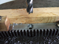
However when I inserted the rack without screwing it down the carriage would run up and down and was actually much better than my original rack system in that I had much less backlash. So decided the best thing I could do was elongate the recess for the screw head and the hole itself to allow the new rack to be installed. So since I don't have a milling machine yet I needed to get my old cheap Busy Bee drill press into play and use it as a very crude milling machine. Needless to say being careful and slow it all worked out. Used a 3/8" endmill to elongate the recess and a 1/4" endmill to elongate the hole. Here are two pictures showing setup and the final product.
As mentioned once this was installed the carriage ran up and down quite smoothly and my backlash was significantly reduced.
So that was the second step forward now for the second two steps back. When I had been doing the threading I talked about earlier I was in back gear for the low speed. Once I was finished I took the lathe out of back gear and decided I would run up the speeds and check to see if the headstock was getting too warm yes or no. So ran it up on the low/high speed for a while then moved the belt to med/high also for a while. Everything was going great so moved the belt to max speed and within 30 seconds the headstock came to an abrupt stop and the chuck proceeded to unthread it self. Managed to turn off the machine and catch the chuck before it fell on the floor and luckily no damage to the lathe bed or the chuck. The head stock though was locked solid. Checked it over and no, the back gear did not re-engage nor did any other pins cause this. This left me with having to disassemble the headstock to see what happened. Once I had it all removed the problem was obvious some how the headstock either spalled or a chip was ingested and came between the headstock and the bearing. Approximately .25" in from the end of the rear bearing, on the pulley side there were three distinct grooves and on the headstock shaft there was some spalled metal. Here are two pictures showing this.
So down I went picked up some 400, 1000, and 2000 grit sandpaper to fix this issue. Carefully placed the headstock in the Boley lathe and on slow speed used a fine file to get rid of the spalled bits of metal. Then used 400 grit sandpaper to carefully smooth that area out until just small grooves left. Then used 600, 1000, 1500, and 2000 grit sandpaper to repolish the areas where the bearings would fit. I also went in to the bearing and smoothed it down as well. There is still a groove in the bearing however no loose material or raised area to catch the headstock. I could grind that area down because there is still lots of bearing surface left in the remainder of the bearing however I think this should work and it will maybe help to allow oil to move around the headstock as well. Here is a few pictures of the finished polishing on the headstock. Actually if you look closely on the second picture you can see my hand holding up the camera as I take a picture so essentially mirror like quality.
Well just need to wait a few days for my order of spindle oil to come in and then I can re-assemble everything and put it back together. With keeping it clean and liberal amounts of oil while re-assembling this I hope not to have any more problems with this. I'll also probably be a little more careful in keeping this area clean and ensuring the oil covers stay closed. Still not 100% sure exactly what caused the problems however I hope this will solve them.
Till next time
Harold


