Wednesday, 18 January 2017

8lbs of Scrap Cast Iron were created today

Well I know it's not the end of the month but I thought I would update you on my attempt at machining a steady rest for the #39 lathe. Everything was going great until I bored a hole today that should have been part of the lock down system. Once it was bored I noticed that it was almost an 1/8" of centre. So it looks like I have to go back to the drawing board and start on the next one. Thank goodness I had three castings made those years ago. Anyway here's the story so far.

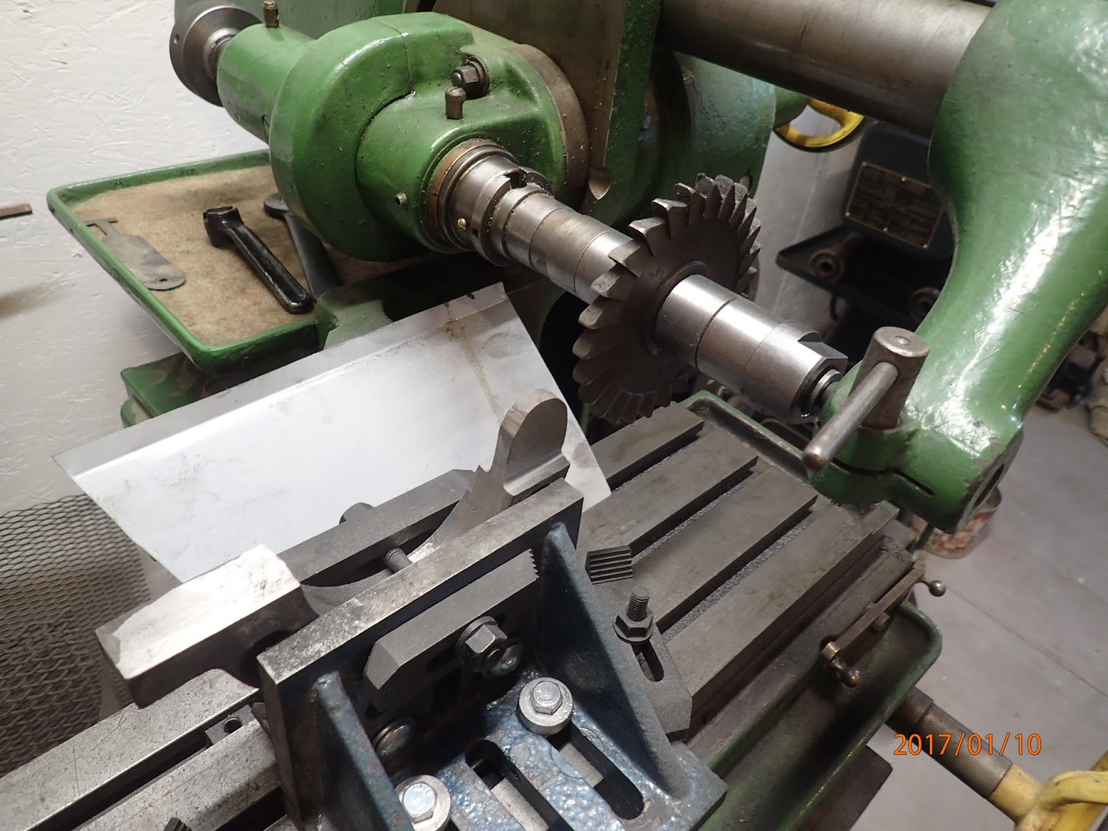
I started by placing the bottom piece of the steady rest on the milling machine and machined the base of the steady rest. This required milling level the two "feet" bottoms and then milling the inner flat portion that lays on the top of the lathe ways. Once that was done I could machine the sides of the two legs to 60 degrees to match the side of the lathe ways. I used a shell mill for the flat portion and then a 60 degree horizontal milling wheel for the leg sides. Here are a few pictures showing the machining operation and then the final fitment on the lathe itself. It did require a little tweaking with a file to get the base to sit nice and firm on the lathe ways. First picture shows me getting the holder parallel to the cutting head. Second shows the two legs flattened and the centre flat machined as well. Third shows horizontal wheel to widen the flat and then the fourth picture shows the 60 degree cutter in action. Last pictures shows the bottom of the steady rest on the lathe after tweaking.


Once that was done I turned my attention to the top half of the steady rest.  First I started work on milling the "inner tang" of the pivoting mechanism. I made this tang .375" thick and would then mill out the appropriate slot on the lower half. When I first made the patterns for casting the steady rest I built the patterns from a whole lot of pictures of an original steady rest and a few dimensions. When I started maching the top section I machined out the slot where one of the steady rest fingers would go. I initially thought the fingers were about 1" wide and possibly 1/2" thick. With this in mind I machined out the first slot. I have since learned the fingers are only about .8" wide and around 3/8" thick. This was brought home when I started to machine the finger slots on the base unit. Anyway I milled out the slot 1" wide and approx .375" deep. I also milled flat the closing tang. Here in the first picture you can see the 1" slot being milled out. For ref I was running at around 100rpm, feeding in by hand with a 50thou depth of cut. It actually worked really well. In the second and third picture you can see the tang being formed by milling off the two sides to get my .375" wide tang.



We now went back to work on the lower half. First we milled out the groove to accept the upper portions tang. I also milled flat the portion that would be part of the closing apparatus on the other side of the steady rest. With that done we started work on milling the grooves for the fingers. I first milled the groove on the latching side of the rest. Once I started work on this groove I realized that I had a width problem and would only be able to mill out a groove about .8" wide. Oh well not an issue, however when I got around to milling out the groove on the other side where the pivot mechanism was I realized that the groove could only be .75" wide and only .25" deep due to the slot I had cut out for the upper tang. After looking at it a bit I realize I can mitigate some of this on the next steady rest by one cutting all the fingers only .75" wide and going .300" deep by realigning how I cut the groove. I initially cut the groove horizontal however it I cut it on the same angle as the finger I have more meat left at the inner side. That was the problem with wider and deeper finger slots. I would intrude into the groove I cut for the pivoting mechanism. So here are some pictures showing the finger slots being milled out as well as showing how I supported it during these operations. 


Once this work was done it was time to bore the hole for the pivoting pin. So after spending some time on a oscillating drum sander it was time to mark out the hole. We then moved over to the drill press to drill out a 5/16" hole for a future pin. This worked out quite well and here are some pictures showing the hole being drilled and then the two pieces mated with a 5/16" bolt acting as temporary pin. I needed to massage the upper tang a little on the sander to get the steady rest to open completely.


Once this was done it was time to thin down the locking support tangs. First I thinned down the upper halfs tang and then worked on thinning out the lower halfs tang. Once both were thinned down to the same with I place the entire unit back on the mill to be able to machine flat the upper portion of the tang on the upper half. Here are some pictures showing the entire process and the use of wood as a securing strap.


So in the mean time I've ordered some bearing bronze to make the fingers and all that's left to do would be to bore out the holes in the finger area for the locking nuts and the adjusting nuts. Lastly we would need to bore the holes and machine the lockdown mechanism that secures the unit to the lathe. Well that's where the title of todays blog comes into play. I went into the shop this afternoon and decided to bore out the longitudinal hole where the locking shaft would go into. I wasn't thinking to well and one I mad the hole to big and two some how I got it off centre such that the lower half is now a useless 8lbs of cast iron. Just for reference here's a picture showing the lower half sitting on the lathe. The hole you see needs to be centred on the gap in the lathe bed and it is not.


 So back to the drawing board. As mentioned luckily I had an extra  couple of castings made initially and now I'll need to use one of them. I plan to use the worst of the two left to try and see if I can remedy this problem . If I can't then I guess I'll use the third one and then look at having a few more castings poured by the foundry. Luckily the foundry is only 3/4's of an hour down the highway.

Well I think I'll drown my sorrows in a glass of scotch and then head off to bed. Work comes a littler earlier tomorrow morning. All the best and hopefully next time I write an update I'll have better news.

Harold

Saturday, 10 December 2016

Ah to be where the weather is warm all day.

Well with the house essentially complete, I have received my final inspection, I can now turn my attention back to playing in the shop. Unfortunately the weather has also turned such that we had a dusting of snow on the ground today. So after doing some painting in the basement I decided to go out to the shop this afternoon and play around with the #39 lathe. This lathe is essentially complete but it does need some tinkering with over time. One of the issues I had was that the belt would rub on the left side of the pulley's both top and bottom. This also meant there was a lot of squeaking  going on as the belt rubbed against the pulley side. So after turning the heat on to take the chill out decided to see what I could do about this.
The first thing I checked was to make sure there was a crown on all six pulley steps. There was a crown however I decided to take a large file and carefully dress the pulley's to clean off the gunk and maybe just crown it a little more. With that down we looked at what was happening. Here is a link to a video I shot showing the problem, you can hear the squeak and you can see the belt on the left side of the pulley. If you look closely at the lower pulley you can see the deflection in the belt. I decided that the belt was not riding true due to the pulley shaft not being parallel with each other. I cannot adjust the headstock so that left shimming the upper pulley assembly. I cut some shim stock down and inserted about 30thous of material. Ran the motor up and noticed a very slight improvement. I then upped the thickness to 80 thous and noticed that the belt was a lot better but that the lower section did not improve as much. I looked at the situation and figured that I might be able to move the headstock a little more to the left If I ground out a bit of the support for the upper pulley assembly. Here are two pictures, the first shows the support arm before grinding with some magic marker indications as to where to grind, the second picture shows the grinding complete.


With the grinding complete the headstock was reinserted and probably moved about a 60-80thous to the left. After a quick run I decided to add a little bit more to the upper spacers. With that complete there was 120thous of spacers under the left side of the upper pulley. Now the upper belt rides very close to the centre of each pulley step. The lower belt is still quite close to the pulley flange but it actually rides a lot smoother. Here is a link to a second video shot after all the adjustments. You can see that the belt runs a lot smoother and there is considerably less squeaking. I can live with this adjustment. Just for reference here is a picture showing the shims that I installed, essentially one washer and some aluminium shim stock.


Well now that that is done I guess it will be time to get back to playing with the machines. I think the first thing I'll do will be to try and finish making the steady rest that I had cast a few years ago. This will entail using the Van Norman milling machine mostly. I think that I'll start that just after the new year so look for updates on this blog to start around the end of January. 

Until then stay warm.

Harold

Wednesday, 30 March 2016

It's been a long time coming

Just wanted to let those of you know who follow this site that the resumption of posts will be happening soon. I finally managed to get both lathes and my Van Norman Milling machine into the new shop. The #39 lathe should be running soon as well as the milling machine. Then we can continue working on finishing up the #86 lathe. My guess is that once a month or unless a lot of work gets down will be my posting cycle. So I hope to see you all towards the end of April with the latest update. For now I'll at least leave you with one photo showing the two lathes and the mill in the new shop.


All the best and see you in a month.

Harold

Saturday, 30 May 2015

A little delayed

Well things did not go as planned and it's been a lot longer than planned trying to finish my house. However the end is in sight. If nothing goes wrong I will have an occupancy certificate within two weeks. Then we can slowly start moving things over. However due to a part time job I now have my time to spend working on the house has been cut in half. I am now guessing the shop will not be cleared out until the end of the summer. Therefore the ability to work on the machinery will need to wait until the fall i believe. I really hoped this would not be the case but it is what it is. Sorry to those who were following this but once we do get setup I will continue this blog with the story of the Hardinge lathes.

Harold