Tuesday 28 March 2017

Minus the painting the first steady rest is complete

Well it's not perfect and I know where improvements could be made but the first steady rest minus some painting is complete. It feels great to be able to say that. I still have some work left on the second one however that will not take to long. So how did we get there. Last month I left of at machining the nut for the lock down device. Well I went back to the steel suppliers and picked up a slightly larger piece of steel. I cut off two square nuts about 1" by 1" by 1/2" and proceeded to drill a hole in the centre for threading. Once this was done I threaded the nut onto it's bolt section and placed it in the lathe and then trued up the top and bottom surfaces. Once that was done onto the lathe to test the lock down setting. After a few adjustments by way of turning the nut we had it in the right location so that a 180 deg turn of the locking rod secured the steady rest to the lathe. Here are a couple of pictures showing the work.


Once we had the capacity to lock down the steady rest completed we went on to milling out the slots where the bronze fingers would ride. This was an other operation that did not quite do according to plan. When I made the moulds used for the casting I am quite sure that I carefully laid out the three finger locations to be exactly 120deg apart. However as you'll see later on the three slots are not quite 120 deg apart. I should have relaid out the spacing before milling however I trusted the casting to be correct when it wasn't. Oh well not a game changer we'll work with it however I'll be a little more careful on other projects. So in order to mill out the slots I first milled a groove at 90deg to the slot layout at the top end of the slot where the adjusting bolt will go through. Once that was done we centred up a cutter on the slot area and but out the slot. I made three passes to get to final depth and then moved the cutter over a little to make one final pass to get the correct width. I ended up making the slots .800" wide which I feel left just enough material on either side to keep it's strength. Here are some photo's showing the operations.


After I had the slots done decided it was time to make up the locking clamp that goes on the side opposite the hinge. This is essentially a U shaped device with a pin through the lower section and a threaded bolt going through the top of the U that clamps against the top section. The U was made from three pieces of steel that I tig welded together. After they had cooled I ground down the weld and rounded some corners before locating it on the lower section and drilling the hole through all three pieces that would hold the securing pin. I then drilled and tapped a hole at the top for the lock down bolt. I handmade the bolt on the lathe using some hex stock that I had. I initially was going to just use a 1/4" bolt and nut as the securing pin however I might just make up a steel rivet just like I did for the hinge pin.


Now that this was done we could get onto milling out the bronze for the fingers. I cut a piece long enough for three fingers and placed it on the mill. After a little bit of time the piece was the correct width and thickness for the slots I had machined. I then cut the bar into the three fingers and spent some time giving the one end a slight roundover. I then marked out the centre and drilled and machined out the slot through which the locking bolt will go. This slot was cut out to 3/8" wide. Here are some photos showing the milling of the three fingers and the last photo shows them laying in the steady rest.


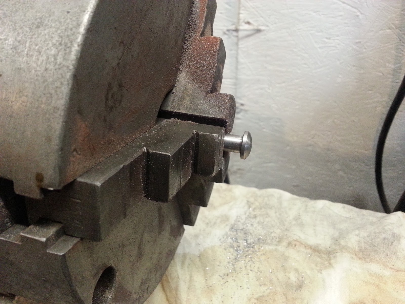
Now we went onto machining a nut and bolt to hold these fingers on the steady rest. Again I made the first bolt and then realized I had no way of securing the bolt as the bolt had a rounded head and I forgot to make the shaft larger enough to mill some shoulders on it that would lock in the slot of the finger. So we had to redesign the bolt and then proceed to make three of them. The nuts were just made from hex stock I had lying around. Here are some pictures showing the bolts under construction and then the pieces lying beside a finger, as well as some pictures showing them installed. First picture is the "mistake" bolt


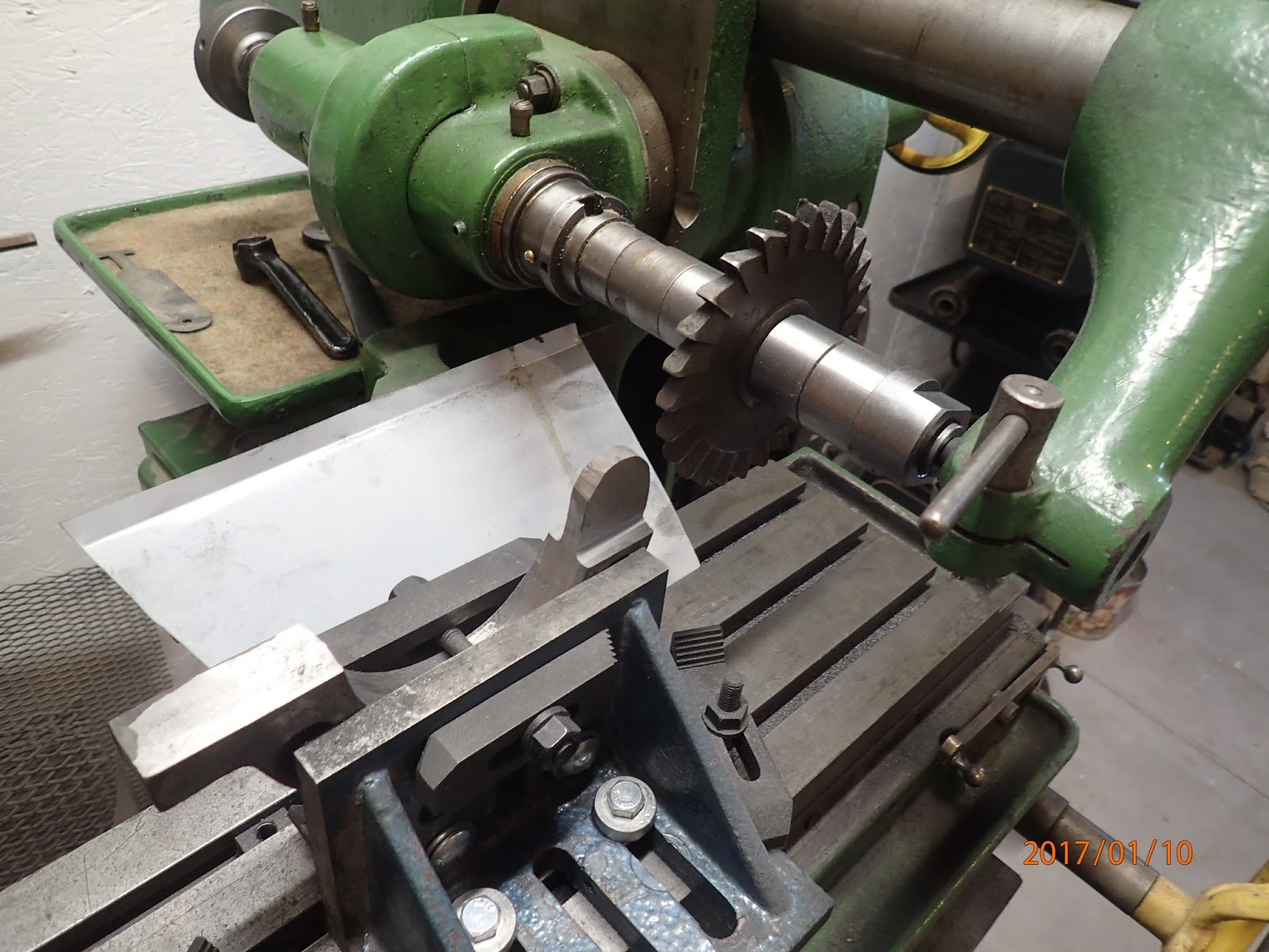
Once that was done I drilled and tapped a hole in the casting at the end of each finger slot to accept a 5/16" threaded bolt I would make. On this one I decided to make a square bolt head that matched a few of the square bolts on the lathe so I could use the lathe wrench to tighten these bolts. To machine the 4 sides of the bolt head I turned to my Milling machine and its dividing head. Here are some photo's showing the machining and the final installation.


So now I need to decide what colour to paint it and then once that's done oil up the remaining surfaces and place it on the lathe for future use. I also still need to machine the fingers and their accompanying nuts and bolts for  the second steady rest however there is no rush as that lathe still is not completely working yet either.

So that's all for now hopefully down the road I'll have more writeups as we complete working on the lathe and possibly start some rebuilding on the Van Norman Milling machine as well.
All the best and see you in the future.

Harold

Sunday 26 February 2017

As the A Team's Hannibal Smith said "I love it when a plan comes together"

Well it was a pretty productive month. As mentioned I needed to restart work on the steady rests and this time I did both side by side. I would first do a machining operation on the worst casting and then tweak it, or not for the second casting. This worked quite well. So I won't go over all the steps to get to the point where I was ready to bore the holes in the base of the steady rest to accept the two pins required to lock it in place. So the first new thing we did was make the rivet that will hold the upper and lower part of the steady rest together. I decided to do this in two parts after trying a more traditional riveting method first. I decided that trying to actually rivet the pin was harder than making two parts with rivet heads and then forcing one into the other with an interference fit. First we made the the long end of the pin that would go through the entire hinge with a rivet head on one end. The other end would have a hole drilled into it that would accept the other end of the rivet. Here are some pictures showing the part being made in the lathe and then lying for display.


The first picture shows the lathe in the chuck after it was cut to diameter, length and had the head rounded over in shape of a rivet. Final operation operation was to drill a hole in the other end and to do this I needed to make a small sleeve that would go over the rivet body and then secure it in the chuck. The second picture shows this small collet. The slot was cut of course to allow the collet to squeeze the rivet and securely hold it while drilling the hole. The third picture shows the two pieces of the rivet. The smaller piece is a few thous bigger than the hole in the longer body and hopefully with some locktite and the interference fit will be a secure fastening for the hinge. The last photo just shows the long pin in the hinge for trial fitment.

Once this was done we could move on to drilling the two hole for the locking pins. First we set the base unit on the lathe and then carefully scribed a line vertically up the middle of the gap in the lathe bed onto the base of the mill. I then calculated where on this line I wanted to drill the hole. After a slight mis-start on the first base we drilled both of the horizontal holes. I then set the fixture up to drill the vertical hole which would intersect the horizontal hole. I lucked out in both cases and got both holes to intersect with most likely no more than 10 thous error. The Horizontal hole is .470" dia and the vertical hole is .750" dia. The vertical hole goes approx .650" deeper than the horizontal hole to allow room for the pin and a piece of spring. Here are a few photos showing the process.


With the holes drilled out it was time to start working on the pins. Unfortunately I forgot to take pictures of the process so I only have pictures of the final product. We started by using a piece of 5/8" hex bar to make the horizontal pin. I initially machined done the surface of the pin area and once complete cut the whole length off. I inserted the pin side in the chuck and gave a slight rounding over to the head of the bolt. I made two of these and here is a picture of the results.


Next we turned to the Vertical pin. This was made from 3/4" round stock so required very little machining on the section that went inside the base. However the bottom end was turned down to .500" to accommodate the tread that would be cut later on. This smaller dia piece was then tapered up to the .750" size and then cut off so that we would have approx 5/16" left on the shaft after the cross hole was drilled for the horizontal shaft. I then placed the pin in the base and through the horizontal shaft marked where the through hole needed to be. Then prayed to the metal gods and drilled out the cross hole. Miracle of miracles after a little bit of filing it fit like a glove. Once this was done I decided to thread the shaft using the BSC thread dies I had and threaded a 1/2" by 26tpi thread. Once this was down we carefully filled down one side of the horizontal shaft where the vertical shaft crossed it. This would allow the vertical shaft to lower by the amount of material moved on the horizontal shaft due to the pressure of the spring above it. Then when the horizontal shaft is turned 180 degrees it raises the vertical shaft and thereby locks the base to the lathe bed with the assistance of a nut that still needs to be made.  Here are some pictures showing the two shafts and how the interact with each other.


Unfortunately when I went out to purchase a piece of steel to make the nut plate I bought the wrong bar stock and will need to pick up another piece on Tuesday. However I did make a temporary nut to try it out. It worked however I am a little concerned that the thread might be to fine a thread for the usage. Once I make a proper nut I will assess the working of the assembly. My worse case will be to make two new vertical shafts and thread a coarser thread on it, most likely 1/2-13tpi. However we'll see how it goes later this week. Even with this minor issue I was quite happy with all the work done. I'm just glad that it worked as expected.  Like Hannibal Smith said " I love it when a plan comes together"

Well that's all for now and we'll see you either end of March or earlier If I get the two units finished sooner.

Harold

Friday 3 February 2017

Second kick at the steady rest so to speak

Well we're back at it. I've started to machine another steady rest after scraping the first one. As mentioned I had three castings made and therefore I still had two left to work on. This time I started working on worst casting of the three. I think this one kinda shifted a bit as the molds were being assembled so the casting is just a little lopsided. So we placed the casting on  the mill and machined out the bottom section where it will sit on the lathe. This actually worked pretty well so decided that while the jig was there might as well take the same cuts on the third casting as well. From now on  I'll continue making the first cuts on the bad casting and if it works then doing the same work on the third casting. I don't have many pictures as the work is the same as was described in the last blog. I will leave you with one picture that shows both castings sitting on the lathe after their bases had been machined out. I needed very little work with hand files to fit them nicely on the base. Majority of filing was just to knock down the edges of the milled surfaces. The casting to the right is the bad one and will be used on the #39 lathe and the one on the left will be for the #86 lathe.


After I took this picture I did a little more work on the castings and I milled a slot in both where the upper section will fit in and pivot around. So over the next few weeks we'll continue working away at them and we'll see where we are when we write another entry towards the end of February.

All the best and Happy Valentine's day.

Harold

Wednesday 18 January 2017

8lbs of Scrap Cast Iron were created today

Well I know it's not the end of the month but I thought I would update you on my attempt at machining a steady rest for the #39 lathe. Everything was going great until I bored a hole today that should have been part of the lock down system. Once it was bored I noticed that it was almost an 1/8" of centre. So it looks like I have to go back to the drawing board and start on the next one. Thank goodness I had three castings made those years ago. Anyway here's the story so far.

I started by placing the bottom piece of the steady rest on the milling machine and machined the base of the steady rest. This required milling level the two "feet" bottoms and then milling the inner flat portion that lays on the top of the lathe ways. Once that was done I could machine the sides of the two legs to 60 degrees to match the side of the lathe ways. I used a shell mill for the flat portion and then a 60 degree horizontal milling wheel for the leg sides. Here are a few pictures showing the machining operation and then the final fitment on the lathe itself. It did require a little tweaking with a file to get the base to sit nice and firm on the lathe ways. First picture shows me getting the holder parallel to the cutting head. Second shows the two legs flattened and the centre flat machined as well. Third shows horizontal wheel to widen the flat and then the fourth picture shows the 60 degree cutter in action. Last pictures shows the bottom of the steady rest on the lathe after tweaking.


Once that was done I turned my attention to the top half of the steady rest.  First I started work on milling the "inner tang" of the pivoting mechanism. I made this tang .375" thick and would then mill out the appropriate slot on the lower half. When I first made the patterns for casting the steady rest I built the patterns from a whole lot of pictures of an original steady rest and a few dimensions. When I started maching the top section I machined out the slot where one of the steady rest fingers would go. I initially thought the fingers were about 1" wide and possibly 1/2" thick. With this in mind I machined out the first slot. I have since learned the fingers are only about .8" wide and around 3/8" thick. This was brought home when I started to machine the finger slots on the base unit. Anyway I milled out the slot 1" wide and approx .375" deep. I also milled flat the closing tang. Here in the first picture you can see the 1" slot being milled out. For ref I was running at around 100rpm, feeding in by hand with a 50thou depth of cut. It actually worked really well. In the second and third picture you can see the tang being formed by milling off the two sides to get my .375" wide tang.


We now went back to work on the lower half. First we milled out the groove to accept the upper portions tang. I also milled flat the portion that would be part of the closing apparatus on the other side of the steady rest. With that done we started work on milling the grooves for the fingers. I first milled the groove on the latching side of the rest. Once I started work on this groove I realized that I had a width problem and would only be able to mill out a groove about .8" wide. Oh well not an issue, however when I got around to milling out the groove on the other side where the pivot mechanism was I realized that the groove could only be .75" wide and only .25" deep due to the slot I had cut out for the upper tang. After looking at it a bit I realize I can mitigate some of this on the next steady rest by one cutting all the fingers only .75" wide and going .300" deep by realigning how I cut the groove. I initially cut the groove horizontal however it I cut it on the same angle as the finger I have more meat left at the inner side. That was the problem with wider and deeper finger slots. I would intrude into the groove I cut for the pivoting mechanism. So here are some pictures showing the finger slots being milled out as well as showing how I supported it during these operations. 


Once this work was done it was time to bore the hole for the pivoting pin. So after spending some time on a oscillating drum sander it was time to mark out the hole. We then moved over to the drill press to drill out a 5/16" hole for a future pin. This worked out quite well and here are some pictures showing the hole being drilled and then the two pieces mated with a 5/16" bolt acting as temporary pin. I needed to massage the upper tang a little on the sander to get the steady rest to open completely.


Once this was done it was time to thin down the locking support tangs. First I thinned down the upper halfs tang and then worked on thinning out the lower halfs tang. Once both were thinned down to the same with I place the entire unit back on the mill to be able to machine flat the upper portion of the tang on the upper half. Here are some pictures showing the entire process and the use of wood as a securing strap.


So in the mean time I've ordered some bearing bronze to make the fingers and all that's left to do would be to bore out the holes in the finger area for the locking nuts and the adjusting nuts. Lastly we would need to bore the holes and machine the lockdown mechanism that secures the unit to the lathe. Well that's where the title of todays blog comes into play. I went into the shop this afternoon and decided to bore out the longitudinal hole where the locking shaft would go into. I wasn't thinking to well and one I mad the hole to big and two some how I got it off centre such that the lower half is now a useless 8lbs of cast iron. Just for reference here's a picture showing the lower half sitting on the lathe. The hole you see needs to be centred on the gap in the lathe bed and it is not.


 So back to the drawing board. As mentioned luckily I had an extra  couple of castings made initially and now I'll need to use one of them. I plan to use the worst of the two left to try and see if I can remedy this problem . If I can't then I guess I'll use the third one and then look at having a few more castings poured by the foundry. Luckily the foundry is only 3/4's of an hour down the highway.

Well I think I'll drown my sorrows in a glass of scotch and then head off to bed. Work comes a littler earlier tomorrow morning. All the best and hopefully next time I write an update I'll have better news.

Harold