Saturday 28 September 2013

Well it's another week and another installment of the voyage to rebuild this old lathe. We had a nice week here such that I could work in the garage after work with the door open watching the neighbour kids play around and the sun slowly set on the horizon. Well actually have to go around the corner of the garage to see it really set however you get my drift. Spent the majority of the week working on cleaning and prepping the whole speed gear assembly. This is a small housing on the left side of the lathe that includes a Slow/Medium/Fast selection as well as the forward and reverse gearing. Here are a couple of before pictures that I took so as to have visual record of where everything went before I stripped it down.


Again almost all the parts are there, just dirty and some with a little coating of rust. As I work on this lathe I have come to realize that when I worked on the first lathe I missed a few oiling holes. I've come to the realization that if there's a hole in the casting fill it with oil. It will go somewhere to lubricate something. It's possible I was just a little anxious on the first one and went a little faster to be able to see the end result however with this one I'm going a little slower and I'm also more cognizant of where oil should be and therefore trying to ensure I have a clean gallery for it to get there. Another thing that came up was that either I'm unlucky with these two machines or there is an inherent weakness in the design of the three speed gear lever. On my #39 lathe this gear lever had been brazed back together and on this lathe the gear lever has also been brazed back together. Here are a couple pictures showing the repair job on the gear lever. I think if I ever get really ambitious I might pull this part apart again and try and make some drawings to make a pattern for this so as to cast some replacements.

 Also heres a little description of the cleaning I'm doing. On the large items I use paint stripper to get rid of the majority of the old paint. Then all the parts go into a large pail and soak in varsol before I pull them out and finish the cleaning. Once they've been cleaned of gunk and old grease and oil I use a small wire wheel on my Foredom flexible shaft grinder to clean all the rest of the rust and paint away. I only do this on the cast surfaces and non critical machined surfaces. All critical bearing surfaces get cleaned and then I use either a scotchbrite pad or brass bristle brush to clean these surfaces. Then once it's all clean I tape it up and spray primer and then paint on the cast surfaces. All machined surfaces get a light coat of spindle oil to protect from flash rusting. Here's just a sample of one piece that is halfway through the cleaning process. Stripped on the right and still painted on the left. As well we also have a couple of pictures showing parts with primer and paint

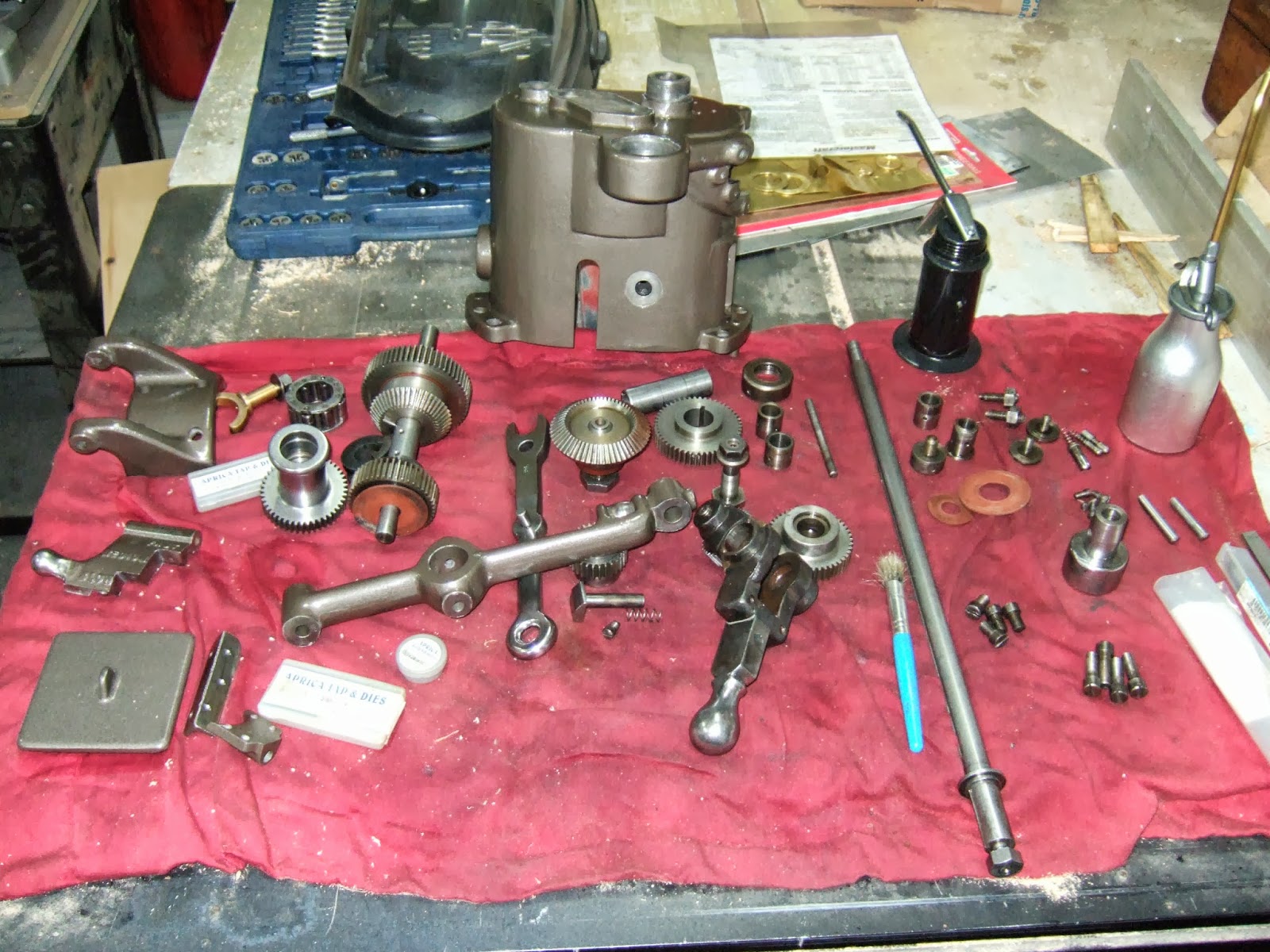
Of course once everything is cleaned and painted, well then we've got to put it together again. Just to show you what we're up against here is a picture of all the parts from the Gear housing assembly. However once it's all back together it looks like the second photo which shows the assembly back on the lathe. It still needs some tweaking and installation of a couple of parts but the majority is there and there was only one requirement to remove and reinstall when I realized I had one of the bearing bushings installed backwards. On this assembly the only things missing were the split lock nut that goes on the leadscrew extension and the bolt and nut that holds the forward/reverse lever in place at the bottom of the arm. Just below the middle of the second picture where the arm touches the edge of the photo.

Towards the end of the week I also started on cleaning the Taper attachment I purchased recently. On every major part of the assembly is stamped a #30 so at one time this taper assembly belonged to Lathe #30. Greg assures me that the lathe body that this came off of has either a #80 or #83 stamped on the end. The last digit is hard to read. So at one time either the previous owner of that lathe rebuilt it with parts from another lathe or he purchased someone else's Taper attachment either because he lost his or it broke on him. I guess without a time machine we'll never know. (where is HG Wells when you need him) Here are a couple of pictures showing various parts of the Taper attachment drying after receiving a coat of primer.

Over the coming week I will try and finish the Taper attachment and then look at machining the 4 bolts required to attach it to the lathe as well I need to machine another setscrew for the gearing assembly mechanism. Finally will need to machine up a split nut that needs to be installed on the extension of the lead screw where it comes out on the left side of the change gear assembly.

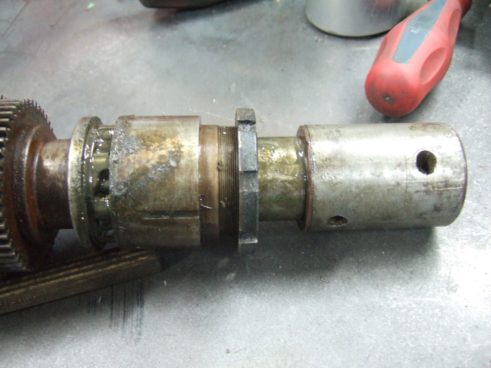
Once the whole assembly was installed I played with the change gear lever and I definitely need to keep pressure on the lead screw, to the left, to prevent the gears from grinding. With this pressure placed on the shaft it again shows the gap by the "U" shaped spacer in the change gear assembly. I might still take the whole contraption apart and at least insert one brass washer and then bolt it together and see what the result is. I really do not like seeing that space there. I'll let you know next week what happened with this. 

Finally last week I asked if anybody from Casa Grande was reading this. I am still hoping for somebody from that town to respond however I did manage to track down a person who used to live there for 20 years. With his help I think we've possibly narrowed down the building that Mr Potter from Practical Machinist believes houses another one of these lathes. I hope over the next week to try and see what luck I might have in tracking down the owner of the property. If I do I will see if he is willing to give us pictures and history on that lathe. Wish us luck. And as mentioned last week if you own one of these lathes or know somebody who does please if you haven't contacted me please do so.

See you all again next week. Lets also hope this nice fall weather stays around for awhile.

Harold


Saturday 21 September 2013

Well it's time to bring you up to date as what's happening in the shop. However as we like to say in the Military first these administrative announcements.  If anybody knows of anybody who owns one of these lathes please talk to them and see if they're in contact with me. If they're not please show them this blog and ask them to contact me via the comment section below. If they or you don't want to leave a comment you can email me directly as well at haroldmulder(at)hotmail(dot)com. As well if anybody reading this is from the Casa Grande area of Arizona please contact me as well. We believe there might be one of these lathes located in an abandoned building in your area. We also have a member of the Hardinge Family that has two lathes. I talked about him last week when I stated I bought a taper attachment from him. He's also asked me to post that he has a few more items that he would like to sell. You can contact me via comments below or the email address above so that I can put him in contact with you. Finally if anybody out there is interested in one of these lathes there is one for sale in the Ohio area. Just leave me a comment that you are interested and I will hook you up with the seller.
      So onto the work we did this week. First thing we did was take what I call the back plate and clean it up. This plate bolts to the left side of the lathe bed and holds up one side of the QC gearbox and to the left of this plate is the forward/reverse and the three speed transmission for gearing. There were a few parts on here that needed to be removed and cleaned and we also pulled out the old Gits oiler plugs and covers. I now have to try and find a company locally that I can buy these oilers from. Gits will not sell directly and McMaster Carr will not sell to individual Canadians and so far I cannot find a company that easily deals in these items. With the last lathe it was a hard time getting them and I think this time as well. Anyway like I said I cleaned up the plate. Primed it and then painted it. Here are a couple of pictures showing this work.


 Once this was done I cleaned up the lead screw as well as the other two rods that go along the front of the carriage. One controls the distance the carriage moves and automatically stops it once it reaches a movable limiter. The second one is the drive shaft for the cross feed portion. Here is a picture of cleaning up the lead screw in the #39 lathe. Used Brass brush and various grades of sandpaper folded over to fit into the thread.


Once we had this all cleaned it was time to assemble the QC gearbox and the backplate to the lathe. Unfortunately between one thing and another I think I installed and removed the backplate a dozen times. Not only that I even had the lead screw installed with its taper pin and then had to remove that as well. Unfortunately the Taper pin had to be drilled out. Oh well I did buy extra's. One of the reasons I had to install and remove it was because of those brass washers I made last week. Initially they seemed to work however once I had the backplate securely mounted there was a noticeable grinding coming from the gear box. So I removed the backplate and the QC gears and moved the washers around in various places to see what worked best. In the final analysis the washers are still on the bench and the QC gearbox and backplate are installed on the lathe. I still end up with a gap inside the QC gearbox by the "U" shaped spacer but the assembly runs smoothly. On another note I noticed something again today. While working back and forth on this issue and comparing it to my #39 Lathe I noticed that the "U" shaped washer was not the same size in both lathes. In the #39 it was wider than in the #86. More credence to thought that these lathes had more handwork than some others. Here are a couple of shots once everything was bolted it on. I left the lead screw loose as you can see.


Luckily enough most items are still with the lathe. The only thing missing so far during this work is some nuts and bolts and the locking collar that goes on the extensions of the leadscrew to the left of the QC. Again I needed to make a bolt to hold the backplate on, there were only two small ones and 4 large ones and I needed another small one. Also I needed to make the smaller bolt that holds the shaft retainer casting onto the lathe at the far right. Not sure about the rest of you however on both lathes that casting was broken in the middle. It still works however not the best design unless it was intentional due to stresses or twisting of the lathe body. I also had to make a couple of setscrews  for the tensioner bracket that sits to the left of the QC box on the extension of the shaft from the leadscrew. This actually worked easier than I thought it would. Just turned down a length of rod, threaded i,t then made a slot in the end for screw driver. Moved the cutoff blade down the thread to the length required, made an initial cut then beveled those edges using a file and then finished the cutoff. The piece to the right of the cutoff blade was the set screw and the piece to the left was ready for the same procedure to make a second set screw. Here's a picture from the lathe showing this.

Well that's all for this week. Hopefully over the next week I'll manage to get the Gearing cluster cleaned up and back together again. Have a nice week and see you on the flipside.

Harold

Sunday 15 September 2013

Well Hello from the Great White North. Been a rather weird week had a few good rainstorms during the week. Had some rather cool days yet we also had 2 days where we broke the record locally for temp and humidity. Oh well you can never figure out Mother Nature you just go along for the ride.
I believe I had a pretty good week in the shop even with an issue which I'll talk about later. Essentially by the end of the week I had the QC gearbox assembly apart, cleaned and put back together again. Here's what we went through.
After taking everything apart last week and cleaning and painting the gearbox casting the first part we worked on was the gear change handle and assembly. This item was in very good shape and all we did was strip it apart, clean all the oil chambers and the assemblies, polish the handle and indicator and then put it back together again. The following two pictures show a before and after.
 Once that was done I removed the gear cluster with it's associated hardware. Once this was pulled apart we found out that somebody had filled the roller bearings with grease instead of oiling it on a daily basis. This is a no-no on these lathes. When these lathes were built oil was used and used daily. Grease came in later when you could ensure the greased area would never be able to have metal chips or filings get in there and imbed themselves in the grease. If this occurred scoring or binding could occur. By using oil you actually lubricated the area as well as washed away any chips the might have gotten inside. Wasn't perfect but it worked for years. Here's a pictures of the items after they were removed.  The first picture shows the entire assembly the second picture shows the end that exits the casting and where the leadscrew would be attached. You can see the grease in the roller bearings just to the right of a U shaped spacer. The roller bearings fit in a holder that has a nut on the right end. This holder fits into the casting and the nut holds it in place. The part on the right has two taper pins and transitions this shaft to the leadscrew.
Once all the parts were cleaned thoroughly it was time to fit them back in the casting which by now had been painted. This is where I came across a problem. I did not notice this earlier however once all the parts were re-installed I had a 70 thous gap between the bearing sleeve which was secured in the casting and the remainder of the parts. In the first picture below you can see the gears on the left, then the U shaped spacer, and then the roller bearings are inside the holder which is in the casting and secured by the nut on the right side of the casting. Next is the transition piece with a fibre washer which is red in colour. You can see the gap in the first picture but the second picture shows it even better. As well you can see in the second picture that the holes are pretty closely aligned for the taper pin. In the third and fourth picture you can see that with the taper pin in place if I slide the shaft to the right which would occur when tightening the assembly, with parts still to be installed, then the gap moves to the inside of the casting where the nested gears sit. The issue with this is that the gap could end up being on either side of the U shaped spacer depending on where it sits. If the gap is on the left of the U shaped spacer then you can start to see the roller bearing races. This would not be a good situation in that if any dirt got inside it would be able to migrate to the roller bearings. After discussions with some other QC owners I decided to make a few brass washers from 30 thous brass I had lying around. I would then install this between the U shaped spacer and the nested gears and hopefully take up most of the gap. The reason for placing the washers between the U shaped piece and the nested gears was that this location did not affect the workings of the gear handle. Had the washers been on the outside of the casting they would have moved the entire nested gear assembly 60 thous toward the tailstock end of the lathe and the gears would not have meshed properly. By keeping the washers inside the gears still mesh. As well by keeping the washers between the U shaped spacer and the gears meant that the other end of the spacer still could be used as it was designed as a seal for the pocket for the roller bearings thereby preventing the ingress of dirt.


To make these washers I clamped a piece of brass onto the drill press and used two different sized hole saws to make the washers. Then I used the dremel tool and some sandpaper to smooth them down. Here are two pictures of the process. In the first picture you can see the effect on the wood of first using a 1" hole saw to cut the ID and then a larger hole saw to cut the OD. Both drills were used without moving the brass thus giving me a rough but usable washer which can be seen in the second picture. As mentioned some sanding and it was good to go.

Once this was all done it was time to put everything back together. Once it was installed with the washers I still had a very slight gap and everything turned quite smoothly. All that's left is to await the arrival of the spiral taper reamer and a few #5 taper pins so that I can securely mount the transition piece back on. In the first picture below you see all the parts lined up awaiting installation with the two washers leaning against the shaft and in the second picture everything is installed with the two washers installed between the gears and the U shaped spacer. Everything was well lubricated and turning smoothly.

 Also I found out that I needed to turn one new screw for mounting this casting. An interesting thing about this I found out today. I only located one of the two screws needed to mount this casting. These screws fit into pockets on the casting before threading into the lathe. No big issue we turn down screw blank and then using a 26TPI die thread the blank. I decided to remove one of the screws from the same area from my #39 lathe to check the length and low and behold although they were the same thread and thread size 5/16" the screw heads were different. The screws on my #39 had a 7/16" shoulder and pocket in the casting and the Screws required for the #86 had a 1/2" shoulder and pocket. So these lathes definitely had some individuality. Just so you can see here are the two screws required. Original on left newly made one on the right.

Also during the week I painstakingly painted the numbers on the door of the gearing section. Here's a picture of the door with the Thread numbers painted in read on it.

As most of you who follow this probably know I do not have all the parts for these lathes. I've had castings made for some parts and some parts will most likely have to be made as time goes by. One of the items missing was the taper attachment. On the #39 lathe I have the base of the taper attachment but nothing else. One of the other QC members out there also has two of these lathes however the second one's bed was chewed up badly by a welding torch and was unrecoverable. Therefore he stripped as many parts as he could of this lathe for future needs. One of these items was the taper attachment. Recently he sent me a picture of his lathe as well as some of the items from the other lathe which included the parts from the taper attachment. I expressed an interest in getting this part and he agreed to listen to my offer. Well I took a closed look at the picture and the original picture of the taper attachment in the 1919 manual and low and behold he had the entire contraption minus a small two pin tool to thread some "button bolts" in . I thought to myself wait a minute I have that wrench. Sure enough I have the wrench and possibly a handle for the Taper attachment so I had to offer a price that he accepted so I could have the entire Taper assembly for one lathe. Once I receive the assembly I will look at possibly trying to replicate the parts needed to complete the taper assembly for the #39 lathe. Just for giggles here's the lonely wrench that forced me to buy the rest of the assembly so they could all be together again.

Well that's all for this week in regards to working on the lathe. I do have a request though for the readers out there. If anybody knows of anybody who owns one of these lathes please talk to them and see if they're in contact with me. If they're not please show them this blog and ask them to contact me via the comment section below. As well if anybody reading this is from the Casa Grande area of Arizona please contact me as well. We believe there might be one of these lathes located in an abandoned building in your area. Finally if anybody out there is interested in one of these lathes there is one for sale in the Ohio area. Just leave me a comment that you are interested and I will hook you up with the seller.

I guess it's time to sign off. See you again next week For you Hockey fans out there the season is almost started better get your lazy boys checked out. 

Harold


Saturday 7 September 2013

Well it's a damp and dreary Saturday here in Trenton. Been grey all day. Good day to work in the shop you'd think, however I have been shellacking the wooden shelf I built for the lathe to stretch between the legs and I did not want to do too much work that would cause dust or metal particles to fall on the wet shellac. However we still managed to get some work done over the past week.

Last week I had the QC change gear casting all primered, this week we gave it a nice coat of paint. As well I carefully cleaned the shelf tray casting for the #86 lathe, again using the Foredom grinder to get into all the small spaces. While cleaning this I noticed that there was a faint impression in the casting. I'm not sure whether they cast these pieces in house or whether they came from an outside supplier. However in the shelf bracket was cast "H Bros 170" along the one edge of the bracket where it is bolted to the lathe. On one of the webs was etched the "170" in larger print. I'm guessing that was the part number for the tray bracket. Once the bracket was cleaned it received a coat of primer and then topcoat. Here are a couple of pictures of the bracket being cleaned, then the casting impressions and then the bracket with a coat of primer.


While these items were drying I decided it was time to work on the wooden shelf that I will insert below the lathe between the legs. I first did this on the #39 lathe and thought it was such a good Idea I would do it again. I still had some nice 1/4sawn white oak around so I planed and laminated a few pieces for the shelf. I then made a support structure that would keep the shelf board straight. Once it was assembled I gave it multiple coats of shellac. Here is a few pictures of the shelf structure being made and then shellacked.


Today I took the shelf casting and attached the two trays I made earlier to the bracket. This bracket which was an original one, actually had threaded bolt holes for securing the shelf. I elected to rivet it together just like I did for my other lathe. I won't go through the whole process again as I discussed this in an earlier blog. However after a few hours work the shelves were riveted to the casting and the whole assembly was mounted on the end of the lathe. I also mounted the wooden shelf as well. Here are a couple of pictures one showing the tray and bracket during work with primer of the bare areas and a final picture showing both items mounted and secured to the lathe.


One last thing I did today was drill 4 holes in the dollies and bolt the lathe to the dollies. I did this just to make the lathe a little more secure since once the overhead drive is installed the lathe will be quite top heavy and it really does not have a wide stance on its the legs.

Well until next week enjoy the weather and remember "Don't worry, Be happy"

Harold


Sunday 1 September 2013

Well it's a new month today and we're a little over halfway through the long weekend. So far for me the weather has been great and we've had a great week. Spent some time in the shop working on the lathe and I also went home to spend some time with the parents and to help my Dad in re-roofing a lean-to shed on his garage. Went home Thursday and by 1300 was on the roof tearing off the old shingles. By 1300 the next day we were on our way to the dump to get rid of all the debris, and the new shingles were installed. We were in no rush and definitely took some breaks and stayed hydrated what with the 35degC weather including the humidex. Came home today around noon and after cleaning up a little spent a few hours in the shop. So here's what we accomplished this week.
I picked up the extra oxygen cylinders I needed and completed the installation of the two trays onto the bracket. The top shelf needed to be done first to be able to properly install the rivets. I turned the assembly upside down and placed a steel block under the rivet heads. I then clamped the assembly to the welding table. I heated up the rivet tails to a cherry red colour and with a few whacks from a heavy hammer pounded the tails flat. I initially attempted to use a steel bar with a small dimpled hole on the one end to try and give the rivet tail a rounded look however this did not work as well as I anticipated so I just resorted to pounding a flattened tail instead. Once the four rivets were installed I carefully ground the top of the rivest smooth with the surface of the tray. This worked quite well and although you can see the rivet outline there is no real lip to catch anything on the tray surface. Well ok maybe your fingernail might catch it but nothing I place on the tray will notice the extremely slight lip. Once the top tray was done then I had to do the same with the bottom tray. This was a little more problematic as trying to clamp the middle of the tray down with the clamps I had was not working too well. However we persevered and eventually all four rivets for the lower tray where installed. One may not be as tight as it could be however it does the job. Here are a couple of pictures showing the top tray after the 4 rivets were installed with some primer over them then a couple shots of the entire assembly being painted.


Once the tray assembly was completely riveted and painted I could concentrate on making the screws. However concentration was slightly lacking when cleaning up from working on the rivet tails. "Note to self never use bare fingers to pick up steel scrap that was used to support rivet tails after being heated to cherry red. Metal is still hot for long time." Turning the 8 bolts needed for both the #39 and the #86 lathe was pretty uneventful. Turned the thread down to 5/16" then used a standard die to thread the rod. Once all 8 were threaded I took a piece of leftover hex rod and drilled and tapped it to the same thread as the bolts. This piece was then secured in the chuck and allowed me the capability of machining all the boltheads to the exact same length by threading them in till the head hit the shoulder of the leftover piece and then I just turned the bolts to length. After they were all turned to length I carefully used a bastard file and sandpaper to round the edges. Here is a picture showing the bolt being threaded into the leftover hex bar prior to being cut to length.

Once all the bolts were cut to length and the firstTray assembly was dry I could install the assembly on the #39 lathe. Here are a couple of pictures showing the tray installed as well as a close up of the bolt head to show the round over. The bolt is shiny because once they were machined I ran them through a buffing process on my grinder. The tray assembly for the # 86 will be done once the tray bracket is cleaned and repainted.


Now we could get back to working on some stuff for the #86 lathe. Today I used a Foredom grinding machine with a small wire wheel on the end to carefully clean the Quick change casting. This casting had previously been stripped using paint stripper and then degreased using Varsol. The wire wheel was used to clean what was left and "polish" up the cast iron prior to it getting a coat of primer. Once all the wire wheeling was done we chased as many holes as we could with taps and then plugged and covered with painters tape the areas that were not being painted. I wasn't too concerned with some areas as once the finish coat is done I can use a razor blade to clean up the machined surfaces. Here are two pictures showing the casting ready for priming and then sitting there with a coat of primer on it.


I thought I'd leave you with this final picture. This is a picture of the #39 lathe as it sits today with her tray assembly attached. 

 Over the next week I'll most likely be working on the QC gear housing and the gearing that goes inside it as well as cleaning the tray bracket casting for the #86 Lathe. Well until next week enjoy what's left of the Labor day weekend and remember the children will be on the streets starting Tuesday going to school so please be careful out there.

Harold